Wireless telemetry configuration
Wireless telemetry / configuration is much more convenient, since the robot complete control can be done in real time while it is in equilibrium, it is therefore easy to modify parameters on the fly and see the real-time behavior.
To reach the highest telemetry range you need the XBee module: also the 2mW series 2 is enough for our application. XBee modules are pre-programmed before using, so you need to download the Digi_XCTU software.
For our needs, the two modules communicate in transparent mode. In this mode, the two modules (and only them) behave as a wired connection. First, put one of the two XBee modules into the USB dongle and set the ID = 0 and MY = 0 parameters, then read the SH and SL values. At this point insert the other module, read SH and SL value and write on the DH and DL fields the SH and SL values read on the previous module: DH = SH and DL = SL. Exchange again the module in the USB dongle and write on its DH and DL fields the SH and SL values read on the second module. In this way the destination address (D) of the first module will coincide with the physical address of the second module (S) and vice versa. At this point the two modules are ready to communicate. Do not forget to set the two XB1TX XB1RX jumpers to “3” to link the module with the Atmel Serial3 used for the telemetry.
Install the second module on Openwheels2 and let the first connected to the PC, start the OpenWheelsGUI_V20 software and select the serial port on the XBee dongle: immediately start reading parameters. You can view all the operating parameters including a real-time graph of the tilt angle, the engine power level and current consumption. A text line at the bottom shows the operating status and any error messages.
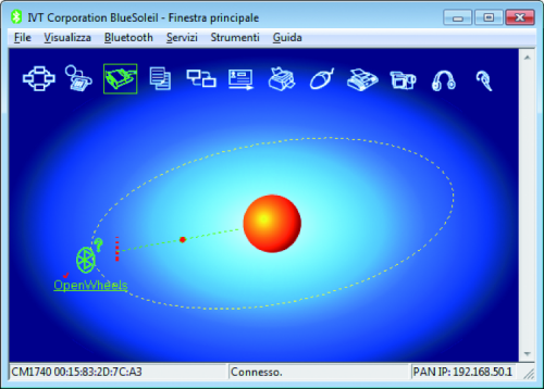
There is also the possibility to set Bluetooth telemetry: in this case it is necessary to equip the Openwheels board 2 with a BT module.
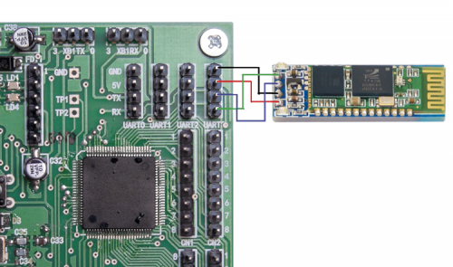
To avoid modifying the sketch we used a Bluetooth module that once configured doesn’t require additional instructions to operate, as the Dagurobot DG010 module, which is always connected to Serial3 through UART3 connector.
This module is sold preconfigured to work in SPP (Serial Port Profile) mode at 9,600 bps; the SPP enables the module to transfer data serially exactly as a cable would do, similar to XBee transparent mode.
For our application, you must set 115 kbps communication speed to “Probot” device name. To do these config you must interface the module to the PC via the USB / Serial converter.
Use a software that can send strings via the serial interface, like CoolTermWin or Arduino SerialMonitor, setting the baud rate to 9,600 bps.
Send therefore the AT string without adding any newline or carriage return: If the module responds with OK means that the communication is established. Change the device name with the
AT+NAMEPRobot
command and the communication baud rate with the
AT+BAUD8
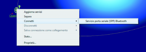
command. The module is now configured and ready to operate in the required mode. The PC must have a built in Bluetooth module or you must use a BT dongle.
Commissioning
With the telemetry software running, you should set all of the PID control parameters to zero and proceed to sensors offset setting; position the robot exactly in balance in a stable and vibration-free status and press the OFFSET button: calibration is automatic and requires two seconds. To avoid having to repeat the operation at every power on, the parameters are saved in the micro permanent memory. Now switch the robot from stand-by to “Go” and reset alarms; you just need to set the right PID parameters to achieve stabilization. There is no reliable and safe procedure to determine the correct parameters immediately; you just need a lot of patience and several trials to come at a satisfactory stabilization. The ideal procedure is that, starting with all parameter at “null”, you just lift the KP parameter until the robot does not begin to oscillate; then lower the KP value so that the robot does not oscillate, then set the KV value. Just with these two parameters, you should ensure the stabilization and only later you will raise the KO value to ensure that the robot maintains its position. Later you can try to raise the KD value to see if the stabilization improves.
With our robot, we simply set: KP = 160, KO = 5 and KV = 12 (the remaining parameters are zero).
Remote control
We can also remotely control the robot’s movements: the basic philosophy is to “fool” the robot by making it believe it is perfectly balanced, while it is actually slightly (we are talking about tenths of a degree) inclined, therefore tending to fall.
It is sufficient to increase or decrease the Pvel variable so that the robot moves back or forth; to make it steer, we need to modify the two motors PWM value by increasing the first and decreasing the other, so that the sum remains constant. As already mentioned the KO and Kdm parameters must be set to zero otherwise the robot will interpret the movement commands as noise and it will try to compensate. Also in this case we have written a PersonalRobotGUI_V10 custom software which allows to keep the main parameters under control and at the same time to control the movement through a simple virtual joystick, mouse operated.


