Wiring diagram
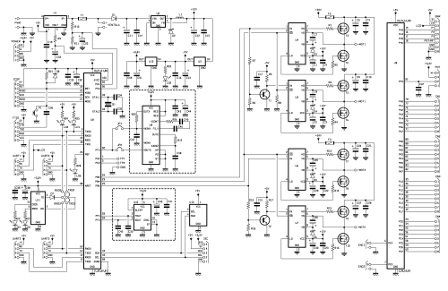
Describing the electrical diagram, let’s start from the power supply stage: the voltage applied to + and – PWR contacts goes to ACS758 chip, that measures the absorbed current, then to the R10 / R11 divider (needed by the chip to measure the battery voltage), to the fuse F1 and to reverse polarity protection diode, which precedes the voltage switching regulator LM2576 (U2) used to lower the voltage to 12V. The board is designed to be powered at 24V and without any changes, accepts down to 11,5V; bypassing the switching, it is possible to accept the lower voltage. On the 12V line there are two linear voltage stabilizers which respectively provide the 5V and 3.3V lines necessary to the microcontroller and IMU module. The two motor drivers, in H-bridge configuration, feature the IRS2184 integrated circuits which uses a capacitive voltage pump to obtain a higher voltage than the power supply one, so as to drive the MOSFET gate.
For each engine, we use two IRS2184 and four MOSFET driven by two signals only: one is the “driver enable (shutdown)” signal and the second is the PWM control signal configured in locked-antiphase mode.
In this mode, the PWM signal goes to both ends of the H-bridge but in phase opposition: so the wheel remains stationary with a 50% duty-cycle. The wheel rotates at the maximum speed in one direction with a duty cycle of 0% and the maximum speed in the opposite direction with the 100% duty-cycle. In case of the balanced-robot, where the wheels have continuous direction changes (to maintain the vertical position), this mode allows the power MOSFET to work with a duty-cycle of about 50%, avoiding very rapid pulse signals as happens in the classic sign-magnitude mode, where a signal is controlling direction and another is the PWM.
With these drivers, when the robot is in the equilibrium position the PWM signal has a very low duty cycle and the direction signal changes continuously. This is not an issue with motors that absorb few hundred milliamperes, but with engines which absorb several amps that can become a real problem. The MOSFETs used in the project are the AUIRF2804 type, supporting up to 200A pulse currents and 10A continuous current, without heating appreciably. We have in any case a fan connector if you prefer the forced cooling.
We have three protection fuses onboard: one by 1A to protect the control circuits and two on the motor power lines; the latter should be dimensioned to interrupt the power circuit in presence of excessive current peaks, usually happening when motors start moving. The microcontroller is an ATmega2560, the same mounted on Arduino Mega, which, compared to ATmega328 (Arduino ONE), has more pins and four serial UART interfaces.
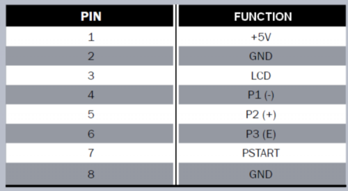
The analog inputs are used for current and supply voltage reading, for the steering potentiometer (if present) and for the analog accelerometer and gyroscope, if they are present. There is a BAR connector to connect a button controller and a LCD display according to Table 1, and a connector for the steering potentiometer (Table 2).
Table1
On the board there are two sockets for the MMA7361 analog accelerometer and for the LPR403 analog gyroscope, and another one for the XBee module; four connectors for the four UART TX/RX signals. Serial0 is the main serial and it is connected to FDTI connector, which can be connected to a USB / serial converter useful for microcontroller programming, while the Serial3 is used for telemetry and is connected to the XBee module socket via XB1TX and XB1RX jumpers; Serial1 is used for the LCD display.
Table2
In the board bottom part there is the InvenSense MPU-6050 digital IMU module connector and that for I²C bus communication port, which connects to any other digital IMU module. There is also a connector for the two encoders input signals and one for the external modules power supply.
All the ATmega2560 unused pins (for this project) are still made available through the CN1, CN2, CN3 and CN4 connectors, if you want to expand any feature. Finally we find the ICSP connector, which, as we shall see, will be used to load the bootloader on the microcontroller.
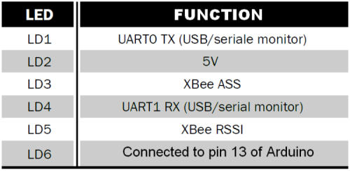
Different LEDs have been implemented to report the operating status, as shown in Table 3.
Table3
The board layout description is done, now let’s move to the practical example by make a really complex balance robot, very stable even in the most critical situations.


