IMU.h file contains functions that allow you to initialize the sensors, to measure offset and actual values. In applications of this type, the firmware is very critical and contemplates various parameters that must assume a precise value depending on the installed hardware; it is sufficient to modify, for example, the robot rod height to change its center of gravity and its moment of inertia; Imagine what can happen for example by replacing motors or varying some weight.
In addition to the usual PID control parameters, there are some less critical but equally important ones that make the difference between a robot that is vertically stable and one that remains vertically even if you apply a weight suddenly; in particular, in MPU6050_init () function check the MPU6050_write (MPU6050_CONFIG, 0x04) instruction that sets the accelerometer and gyro data filtering to 20Hz frequency (parameter DLPF_CFG = 4) ensuring a cleaning read from the unwanted noise.
If the robot had been smaller and you need faster reaction times, this value would necessarily rise (lower DLPF_CFG parameter). Another relatively important parameter is the cutoff frequency of the complementary filter that merges the sensors readings.
The line that defines it is this:
float Comp_Filter_Constant = 0.01
lower values slow down the angle measurement (but attenuate the noise more) while higher values allow to obtain faster angular measurement, but more affected by noise.
The section that manages the encoder is contained in Encoder.ino file, an ex-novo implemented section for OpenWheels2: in balanced robot, it is important not only the vertical stability, but also the keeping of a precise point in relation to the ground, otherwise it can happen that the robot moves randomly in the room because of some sensor drift. The encoders provide information about the wheels’ rotation, so you can evaluate when the robot moves. Using the encoders on both wheels we can also obtain information on the rotational difference between the two, which would lead the robot to rotate on its vertical axis because of motors behavior light differences.
To avoid that, we set the variables WheelsPos (DEG), which provides the position of the wheels in degrees, WheelsVel, which provides the wheel rotation speed in degrees per second, and the encoderDif, which provides information on the rotation difference between the wheels in degrees.
To each of the two encoders is associated an interrupt:
<span style="font-weight: 400;">attachInterrupt (0, EncoderLeft, </span><span style="font-weight: 400;">
 </span><span style="font-weight: 400;">FALLING); // pin 2 int0 encoder (ENC1)</span>
<span style="font-weight: 400;">attachInterrupt (1 EncoderRight, FALLING); // encoder pin3 int1 (ENC2)</span>
To find out if the wheel is turning clockwise (and then increases up the counter) or counterclockwise (decreases the counter) we have to use both the quadrature signals provided by the encoder. The second signal is then connected to a board digital input and when read during the interrupt, it provides info on the wheel rotation direction (see Listing 2).
Listing2
void EncoderRight()
{
// If pinA and pinB are both high or both low, it is spinning
// forward. If they’re different, it’s going backward.
if(PINL & 0b00000010)
encoderCounterRight++;
else
encoderCounterRight--;
}
The file named PID.ino is the heart of the whole system, because it contains the lines of code needed to stabilize the robot (see Listing 3). It is, ultimately, a calculation which takes into account the different contributions according to parameters which the user must enter in a very precise way. Let’s look at the meaning:
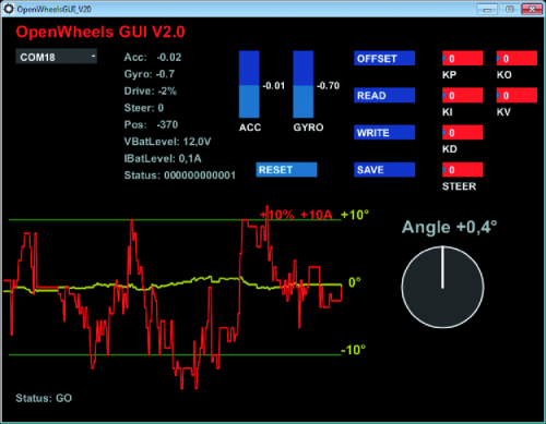
– Pval, controlled by the parameter KP, is the proportional value (the more the robot tilts the more is necessary to compensate);
– Ival, controlled by KI parameter, is the additional value and is used only in SegWay clones to control the function to move ahead at a constant speed keeping the handlebar in rest position
– DVAL, controlled by the parameter KI, is the derivative value and its effect is felt as much as greater is the tendency to fall down;
– Ppos, controlled by KO parameter is the proportional value for positioning; the greater this value, the greater the accuracy with which the robot maintains its ground relative position;
– Pvel, controlled by the parameter KV, is the value which, together with the PPOs value, avoids that the robot moves away from the initial position.
Listing3
Pval = float(KP) * Angle;
Ival = float(KI) * Integral;
Dval = float(KD) * Gyro_Rate;
Ppos = float(KO) * wheelsPos;
Pvel = float(KV) * wheelsVel;
drive = Pval + Ival + Dval + Ppos + Pvel;
drive = drive * VBatAlim/VBatLevel; // for compensate Battery level
drive = constrain(drive, -250.0, 250.0); //limit drive values
In the telemetry software you can set the STEER parameter, useful for setting the steering sensitivity when the project is a Segway clone.
An additional parameter called Kdm allows to keep the robot original orientation compensating for differences in wheel rotation. Obviously, the last three values must be reset to zero in all cases in which you want the robot to move, perhaps because remote-controlled.
By analyzing the code there is also a line used to compensate the battery charge level:
drive = drive * VBatAlim / VBatLevel
In fact, the actual power transferred to wheels depends on the level of battery charge and can be different from the expected (calculated) power level. Since we don’t want the robot to behave differently according to the battery charging level, this parameter is very important. The Motor.ino file (Listing 4) contains settings and functions to manage the engines, first of all the setting of Atmel internal registers, in order to control motors with a PWM signal at high resolution (10bit) instead of the 8bit used by default in Arduino; also the PWM frequency is set to 16 kHz, ensuring a more fluid and silent movements. Also in this section, there are two other parameters denominated steerSensibilty and speedSensibility that, as suggested by their names, define respectively the steering angle and the speed sensitivity, if the robot is remotely controlled (Listing 5).


