The firmware
The firmware is derived from the original OpenWheels one, improved and enriched with new features. To upload it, you must install a bootloader on ATmega: we can use a dedicated programmer or a common Arduino board used as a programmer.
In the latter case, run the Arduino IDE and load ArduinoISP.ino , set “Arduino Mega2560 or Mega ADK” as target board in Tools menu> Arduino type, then set Arduino as programmer (Tools> programmer> Arduino as ISP).
Table5
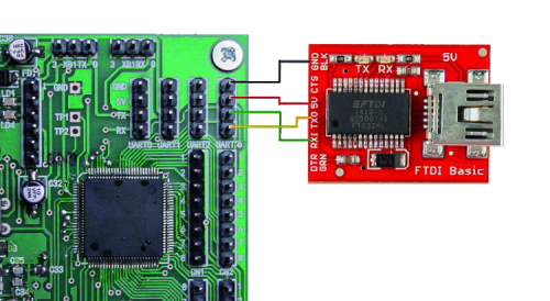
At this point start the upload with Tools> Write Bootloader. When done (requires a few minutes) disconnect the programmer and connect to the board directly from the PC via the FDTI connector with the aid of a USB / Serial converter: your board will be seen on the IDE as an Arduino Mega.
To verify that everything is working, load the Blink.ino example sketch and check if the LD6 LED flashes.
For now, you can omit the XBee module and ensure that the IMU module is correctly installed; you can then do some tests to make sure everything works (we recommend you do so before installing the board and make connections).
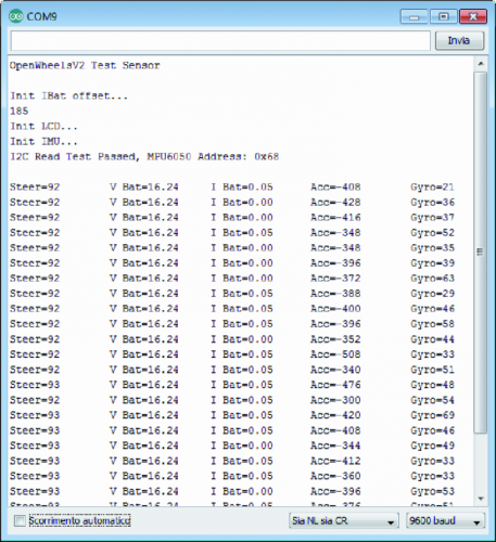
Let’s test the sensors with the sketch named PersonalRobot_TestSensor.ino available together with the project files on www.elettronicain.it . The collected data will be displayed directly on Arduino SerialMonitor in a raw format, without any post-processing. With a simple jumper you can simulate the buttons by shorting P1, P2, P3, PStart inputs to the GND pin; connecting a serial display to BAR connector + 5V, GND, LCD pins you can test it. Please note that the LCD display is supported in both hardware and software, but not used in this project because, as we shall see, we expected more for the data display systems. If the motors are connected, you can test them by loading the OpenWheelsTestMotorV2.ino sketch. Motors are controlled directly by typing characters through the SerialMonitor. The important thing to check is that motors rotate in the correct direction and that the robot moves ahead when the wheels spin clockwise.
One of the most important innovations over the previous version is the use of a digital IMU module based on Invensense MPU-6050, which features an accelerometer and a gyroscope both three-axis, in addition to a suitable microprocessor to process the acquired data. The precision and resolution are greatly increased and the noise level, main villain for any accelerometer, here is very low.
This module which is often found on the market as breakout board with the GY-52 part number, is an excellent compromise between performances and cost; also its I²C communication interface is perfect for pairing with Arduino. As always, the accelerometer and gyroscope data must be merged together in order to minimize the inevitable gyroscope offset drift and to limit the accelerometer noise; between the various solutions, the complementary filter was effective and easy to implement.
The firmware required to operate our robot is called PersonalRobot_V10.ino and can be downloaded together with all the other project files. Let’s start by saying that in the robot, the control board is placed vertically, but nothing prevents you to place it horizontally; in which case you must configure the firmware uncommenting the right code instruction:
<span style="font-weight: 400;">// horizontal board</span>
<span style="font-weight: 400;">//Wire.write(MPU6050_ACCEL_YOUT_H);</span>
<span style="font-weight: 400;"> </span>
<span style="font-weight: 400;">// vertical board</span>
<span style="font-weight: 400;">Wire.write (MPU6050_ACCEL_ZOUT_H);</span>
The sketch is divided into blocks, each of which has a distinct file according to its function;
PersonalRobot_V10.ino contains the main code that calls all the necessary functions.
The main loop contains only the function calls and the cycle time measurement (see Listing 1).
Listing1
void loop()
{
time2=micros();
dt = float(time2-time1)/1000000.0; //cycle time
time1=time2;
SoftStart();
EstimateAngle();
EstimatePos();
Status();
PID();
SetMotor();
SetZero();
Telemetry();
if (digitalRead(P1_pin) == 0)
{
// reset error
statusFlag=0;
errorIMU=0;
Integral=0;
encoderCounterLeft=0;
encoderCounterRight=0;
}
delay(18); //about 50Hz
}
The entire stabilization cycle lasts approximately 2 ms, but with a delay function we bring it to a more reasonable 20 ms, or 50 times per second. The telemetry impacts heavily on the cycle time, which in any case is recalculated in each iteration. In EEPROM.ino file there are the functions required to read and write the ATmega2560 EEPROM: in our case, all of the PID control parameters and sensors offset values.


