
Listing4
void initMotor()
{
pinMode(ShutDown_pin, OUTPUT);
digitalWrite(ShutDown_pin, LOW); //ShutDown driver at startUP
pinMode(PWMLeft_pin, OUTPUT);
pinMode(PWMRight_pin, OUTPUT);
// Phase and Frequency correct PWM on TIMER1
//PWM_frequency = (16000000)/(2*Prescale_factor*ICR1)
//ICR1=(16000000)/(2*Prescale_factor*PWM_frequency)
// ICR1=400 fPWM=20000
// ICR1=500 fPWM=16000
// ICR1=666 fPWM=12012
// ICR1=1024 fPWM=7812
TCCR1A = _BV(COM1A1) | _BV(COM1B1) ;
TCCR1B = _BV(WGM13) | _BV(CS10);
ICR1=500;
// **********************************************************************
// limit for driver compatibiliti (5% di ICR1A) < drivePWM < (95% di ICR1A)
// stop motor driver=stallMotor=ICR1/2;
// **********************************************************************
maxPWM = float(ICR1)*0.80/2; //0.95
stallMotor=ICR1/2; //25
OCR1A = stallMotor; //0=0% ICR1/2=50% ICR1=100%
OCR1B = stallMotor;
}

In this section you will also find the motor dead zone compensation, which is the voltage level below which the wheels do not turn for internal friction and losses. For example, if the robot needs a 5% engine power to be stable but the corresponding voltage level is within the dead zone and is not sufficient to overcome the friction, the wheels will not turn. This results in the robot tending to fall down thus requiring a further correction, causing an uncertain balance. A simple test with the robot leaning against the ground will allow you to determine the minimum power value needed for the robot to move. The code line that defines this parameter is:
int deadZoneMotor = 10.
The section SerLCD.ino is not used and has been left for compatibility with previous hardware.
Listing5
void SetMotor()
{
Steer = steerSensibilty * float(int(dataX)-127);
Speed = speedSensibility * float(int(dataY)-127);
drivePWM_L = int( (drive*goStart) - Kdm*float(encoderDif) + Steer );
drivePWM_R = int( (drive*goStart) + Kdm*float(encoderDif) - Steer );
// compensate motor dead band
if (drivePWM_L>0) drivePWM_L += deadZoneMotor;
if (drivePWM_L<0) drivePWM_L -= deadZoneMotor;
if (drivePWM_R>0) drivePWM_R += deadZoneMotor;
if (drivePWM_R<0) drivePWM_R -= deadZoneMotor;
dutyCycleLeft = stallMotor + drivePWM_L;// + Steer;
dutyCycleRight = stallMotor + drivePWM_R;// - Steer;
dutyCycleLeft = constrain(dutyCycleLeft, stallMotor-maxPWM, stallMotor+maxPWM);
dutyCycleRight = constrain(dutyCycleRight, stallMotor-maxPWM, stallMotor+maxPWM);
OCR1B = dutyCycleLeft; //set PWM SX 250+-250
OCR1A = dutyCycleRight; //set PWM DX 250+-250
}
The telemetry.ino file contains the functions used for communicating with the board; specifically, to request data or set of parameters. In any case, it is the external equipment that must request for data, as Openwheels2 don’t send any data automatically; see, in this regard, Table 6.
Table6

Additional fine tuning parameters are used to control the operating state and alarms; as an example, these three voltage values related respectively to the maximum, minimum and nominal power voltage:
<i><span style="font-weight: 400;">float VBatLmax = 12.6;</span></i><span style="font-weight: 400;"> </span><i><span style="font-weight: 400;">// Max batt Volt</span></i>
<i><span style="font-weight: 400;">float VBatLmin = 11.5;</span></i><span style="font-weight: 400;"> </span><i><span style="font-weight: 400;">// Low batt volts</span></i>
<i><span style="font-weight: 400;">float VBatAlim = 11.8;</span></i><span style="font-weight: 400;"> </span><i><span style="font-weight: 400;">// Nominal batt Volt</span></i>
<span style="font-weight: 400;"> </span>
These values are used, as well as for alarms, even for the engines power compensation function.
Notice that because of the power drivers, the minimum operating voltage cannot be less than 11.5 volts, worth the impossibility of bringing the MOSFETs in the ON state. Another value is the maximum current before engines safety shutdown.
The function operates in about 20 ms: it’s not the same speed of fuses, but it offers good protection in most cases:
<i><span style="font-weight: 400;">float IBatMAX = 3.0;</span></i>
<i><span style="font-weight: 400;">// IBAT MAX for MOTOR shutdown</span></i>
Additional protective measures impact the variables shown in Table 7.
Table7
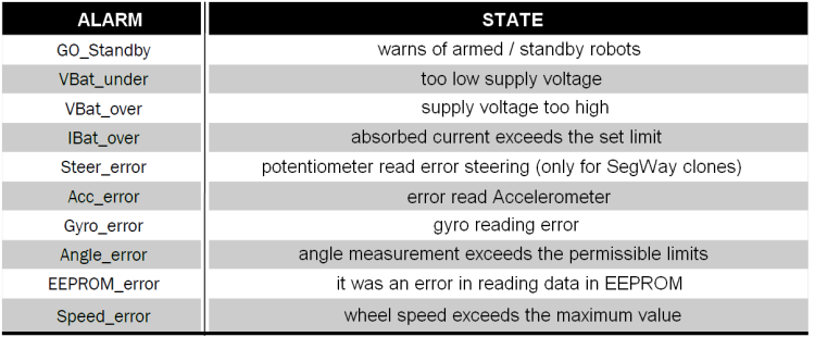
The first bit of statusFlag does not contain an error, but indicates whether the robot is in standby or armed state, i.e. “up and running”. This state change is operated by the switch.
In the standby state all systems are fully functional, including telemetry, but the driver is disabled and the wheels cannot turn: you can then manage the robot without doing damages.
LD6 LED flashes in case of an error state; you can reset the alarms by pressing the reset button (or by remote control) only.
Given the complexity of setting parameters and the need to visualize the operating condition, we have implemented a special software (OpenWheelsGUI_V20) for the remote management of all major operations, allowing you to view all the telemetry data graphically. The software was written by using Processing, because it is a development environment that supports several operating systems.
In order to use the configuration software, you have to install the USB / Serial converter, so as to communicate with the board using your Serial3 microcontroller interface, available on UART3 connector: simply wire the TX, RX and GND lines; the + 5V is not necessary because the board has its own power supply. The software is very intuitive and once executed, simply select the serial used for communication: the software will, at regular intervals, poll the robot.
All major data is displayed: the tilt, the current consumption and the engines power are also visible on a chart. Red fields allow parameter entry by simply dragging over the mouse pointer. The RESET button allows you to reset all the alarms, OFFSET allows the sensor offset check, READ commands the reading of currently used PID parameters, WRITE sends the parameters, while the SAVE button saves in the microcontroller EEPROM memory the currently used PID parameters.


