The robot mechanical part
We start from the mechanical parts, printed with our 3Drag and appropriately designed to house the electronics. On the base we’re going to fix motors, battery and OpenWheels2 control board. We will fix also an aluminum rod we can use as a support for a small tray put on robot’s top and that can contain objects or, as we did, drinks; nothing prevents you from applying anything else.
The control board should be connected to the following devices:
– 2 motors with encoder and wheels (2846-BALANCINGBOT);
– Li-Po Battery 1800 mAh / 11.1 V (5400-LIPO1800);
– male / female connector (7300-TCONNMF);
– unipolar switch button (8220-8701);
– unipolar deviator lever for c.s. at 90 ° (8220-TS-8);
– 2 XBee 2mW modules, Series 2 (6168-XBEE2MW);
– XBEE USB EXPLORER (6168-XBEEDONGLE2);
– Bluetooth DAGU controller module (2586-DG010);
– 3-axis accelerometer + 3-axis gyro (2846-MPU6050);
– converter FTDI USB / Serial 3.3V and 5V (7300-FTDI5V);
– fuse (F2) 1A;
– fuse (F1, F3) 5A.
The XBee modules and Bluetooth are used for telemetry. The components are all available in our store.
If you were using a long rod for the tray, it may be necessary to provide a small weight of about 100 g to balance the weight at the rod base, due to motors and battery; we could have placed the batttery high up, but that would require long cables that would have introduced a deleterious electrical resistance.
Although it is not intuitive, the weight placed on top enhances the stability while minimizing small oscillations due to the materials weakness.
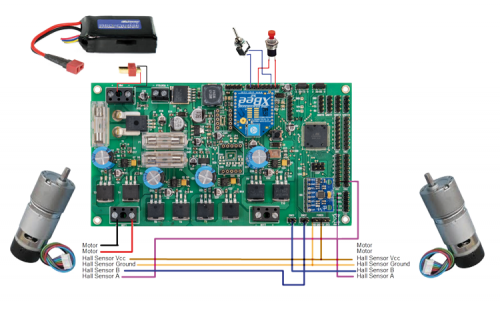
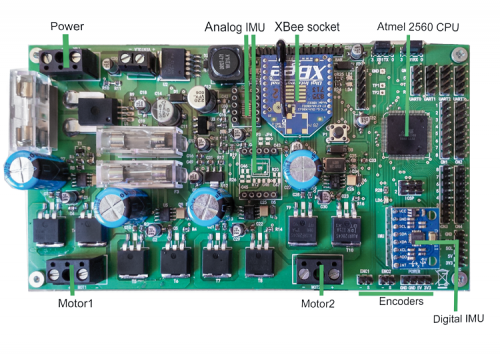
At this point, you can fix the motors to the 3D printed substrate, their related wheel and the electronic board, as shown in pictures; The only precaution is to fix the board properly. As regards the electrical connections, we must be very careful, especially for engines that have the encoder incorporated; refer to Figure.
There is a switch (connected as shown in Table 4) that will be used to activate the robot and a button to reset the alarms. If you want, you can put a power switch in series to the battery shows the wiring.
Table4


