CN1 is the connector used for the logic and for the serial and I²C communication. As for the micro USB connector, it is used both for giving commands to the controller, and for the microcontroller’s programming via Arduino’s IDE.
To load the bootloader you will have to necessarily proceed like this: don’t connect anything to the CN2 connector and leave the connector used for the power supply selection unwelded, or keep a 5V voltage setting. If you have a dedicated programmer for Atmel devices at your disposal, you will already know the procedure; otherwise please equip yourselves with an Arduino Uno board, that you will use as a programmer.
The OMC21 controller’s ICSP connector will have to be pin-to-pin wired to Arduino’s ICSP connector that is used as a programmer: that is to say, pin 1 goes with pin 1 and so on. The Pin 5 (the reset pin) of the controller’s connector, that we have to connect to Arduino’s pin 10, is an exception. At this stage we may connect the Arduino board to the USB port; the OMC’s power supply LED will turn on to indicate its proper power supply.
Please load the Esempi-ArduinoISP sketch on Arduino, it will enable Arduino to operate as a programmer; now open the Strumenti-Tipo di Arduino menu and modify the programming target in Arduino Leonardo. Please select the Arduino as ISP programmer and then boot the bootloader programming by clicking on Scrivi il bootloader. Please wait for about a minute for the operations to be completed.
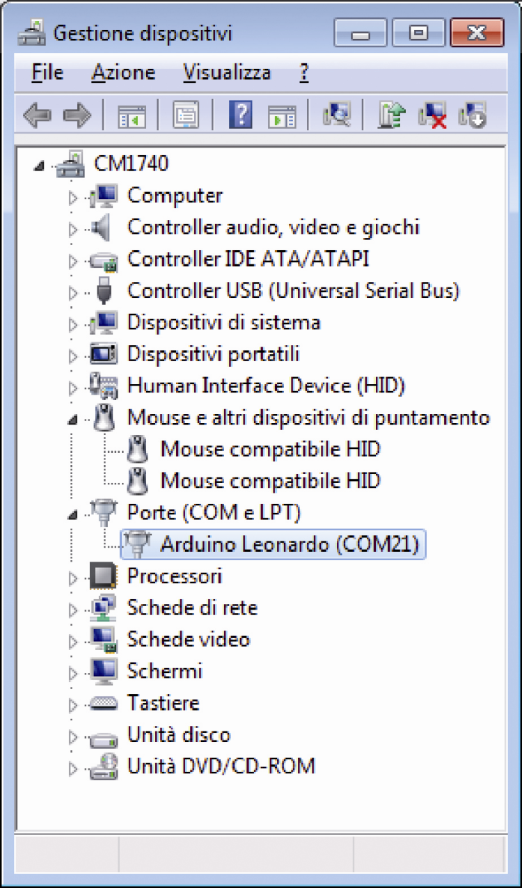
The ATmega32U4 integrated circuit has a main serial port that depends on the internal USB module; at a programming level nothing changes in comparison to Arduino, if not for the fact that a USB/serial converter is not needed since it has already been implemented inside it. Thanks to the bootloader, as soon as the OMC21 is connected to the USB port it will be recognized as a peripheral and a virtual serial port will be created: it will be labeled as Arduino Leonardo and a name will be given to it: in the case of the figure, it’s COM21.
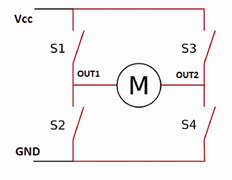
At this stage your OMC21 can be completely managed via USB and it is possible to load (by means of Arduino’s IDE) the management sketch named OMC21.ino; let’s describe now how this management software operates, in particular as for the H bridge’s control. Let’s start by saying that the management of the four static switches represented by the transistors can be carried out in different ways, depending on the function we want to obtain. Let’s take figure as a reference: in a simplified way, it represents the H bridge’s four switches that have been implemented by means of MOSFETs in our driver.
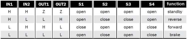
Let’s read carefully the LV8405V-D driver’s data-sheet in order to obtain the truth table concerning the switches’ (S1-S4) and outputs’ (OUT1 and OUT2) state, for each possible input combination; the letter L indicates a low logic level, while the letter H indicates a high logic level.