
The very low resistence of the MOSFETs used for the motor’s control (only 0,75 ohm) allows for a very high performance and sports a very limited heat dissipation.
To create a motor control that is easy to interface and program, it is however needed to couple this IC to a duly programmed microcontroller: the choice fell on the ATmega32U4, manufactured by Atmel: the same used by Arduino Leonardo board. Unlike Arduino Uno that has the ATmega328 microcontroller, the ATmega32U4 is used in the Leonardo board, since it internally implements all the hardware needed for the USB communication, thus eliminating the need to use a USB/serial converter, externally. The features are usually better than those of the ATmega328, since it is a last generation component; moreover the microcontroller is perfectly compatible with Arduino’s development environment (IDE). A few more components and here we have at our disposal a small, cheap motor control, one that has interesting features:
- double H bridge configuration, needed in order two drive to DC motors or a bipolar stepper motor;
- power section’s voltage: 3 ÷ 15V;
- logic power supply voltage: 3 ÷ 5V;
- output current: 1,4A direct current (2,5A as a peak) for each motor;
- interfacing via USB, serial, I²C-Bus communication;
- compatible inputs at 3,3V and 5V;
- selectable power supply modes: internal and external at 3,3V or 5V.
Since we wanted a very flexible controller, we looked after the power supply section in particular; we wanted a driver that could be compatible with logics operating at 3,3V and 5V, one that could be powered by the same voltage of the command logic, and that could power an external logic, so to work with the same power supply levels.
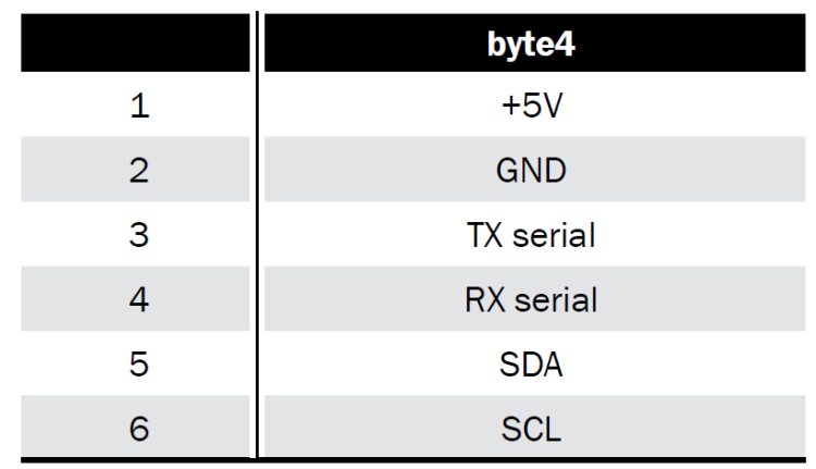
As you can see from the circuit’s diagram (you may find it nearby…), two low-drop-out voltage stabilizers (a low input-output voltage drop) have been taken into account: they are used to obtain the power supply voltages at 3,3V (U3 deals with it) and 5V (U2 deals with it). The selection of the power supply voltage needed happens by joining the corresponding holes of the JP1 jumper with a drop of tin. By welding the central hole with the 3V3 one, the power supply voltage is set at 5V, while connecting it to 3V3 the voltage is set at 3,3 volts. As per specifications of the ATmega32U4 integrated circuit, the operation at 3,3 volts is guaranteed only with a 8MHz quartz, to which a corresponding bootloader has to be coupled. The selected voltage is also available on the CN1 connector and can be used to power an external logic, as an Arduino board (please see Table). The main power for the whole circuit is drawn from the power supply line of the VM motors.
Another possibility takes into account that we might not weld any CN3 connector’s hole, in this way the VM power supply will be used to power the motors only, while the power supply for the ATmega32U4 will have to be applied externally, from the command logic, via the CN1 connector; in this case it is needed that the command logic is powered separately.
As regards the power supply connector, it takes six contacts into account: of them, two are used as power supply and are named VM and GND, two are used for the first motor (1A and 1B) and as many for the second one (2A and 2B). The VM power supply will obviously have to be compatible with the motors’ power voltage and will have to supply enough current to power the motors. The ICSP connector is the one used for programming: later we will explain how to use this connector to load the bootloader in the ATmega32U4.


