
Controller’s usage
As for the connections and the practical usage, many combinations are possible as regards the power supply for the control logic and the LV8405V-D integrated driver’s power section; In figure shows the general connection of the two DC motors (as for the bipolar stepper-motor, each winding goes in the place of a motor) and of the board power supply.
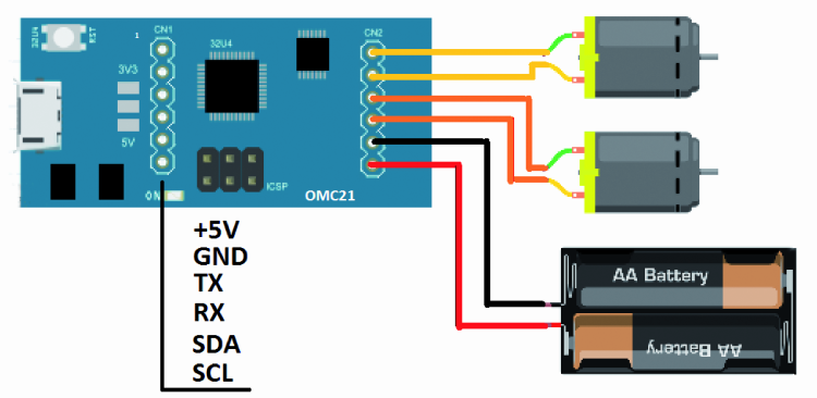
On the other hand illustrates how to set up the 3V3/5V jumper (in this case we have to leave it completely open), used for the power supply selection concerning the microcontroller and the LV8405V-D driver’s logic, so that it is directly drawn from the USB connection; in the same picture the motors are powered via VM.
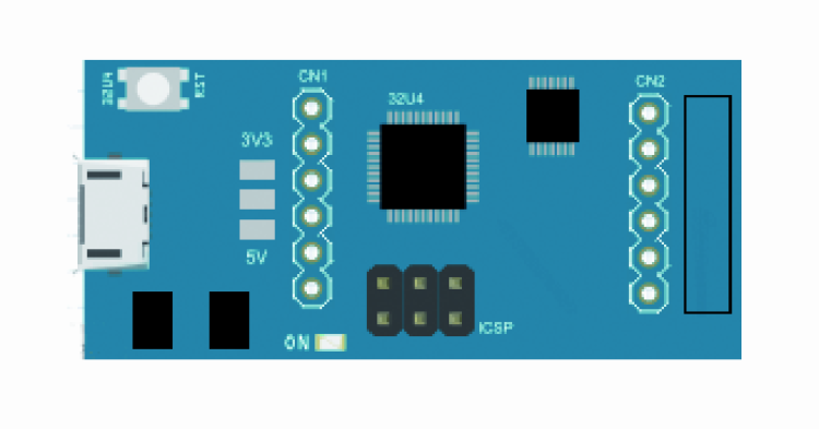
This figure shows how to set the jumper if you want to power the power circuit by means of VM, and the microcontroller and the driver’s logic via the 3,3 volts obtained from the same VM, by means of the U3 regulator (the jumper has to be created, taking care to close it with a tin drop).

In figure we propose a jumper’s setting, having the microcontroller and the driver’s logic powered with the 5 volts that the U2 regulator obtains from VM (circuit input voltage and power voltage).


