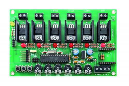
All of the functions of the U3 module are managed via serial interface, by means of specific instructions given by the microcontroller: those concerning the volume are generated by reading the ATmega’s ADC, when it samples the voltage on the R6 trimmer’s pointer. We also considered the usage, among the reproduction management commands (Play, Stop, Pause, FWD ecc.) only of the Play/Stop one, that has been implemented by means of the three buttons connected to the microcontroller, via the PD2, PD4 and PD7 lines (all of them are initialized as inputs supplied with an internal pull-up); all of them have the same function, that is to say, the one of enabling/disabling the audio. More precisely, the pressure of one among the P1, P2, P3 buttons (when a track is being played) determines the stop of the same, and a following pressure makes the track previously stopped to start from the beginning.
When the audio track is being played, the LD7 LED is turned on by the microcontroller’s PB5 line (that during the normal operation is used as an output); the PD0 and PD1 lines, depending on the UART, are coupled to the U3 module by means of resistors, so to avoid that – during the programming (that is to say, when the USB/Serial converter is applied to the board) – interferences might arise between the voltages of the two modules.
The files found on the SD Card must compulsorily have the name in the following format: 001.mp3, 002.mp3, 003.mp3 and 004.mp3. The first file is recalled during the day phase, the second one during the sunset, the third one when the hearths are turned on, regards the flickering lights) and the 004.mp3 file is recalled when the dawn comes. For this reason, you will have to rename the track you wish to be played during the day phase as 001.mp3, the one for the sunset as 002.mp3, the one for the hearths being turned on as 003.mp3, and the one to be recalled when the dawn comes as 004.mp3.
During the passage between a phase and the other, the playback volume will be gradually decreased until the end of the track, while the playback of the following track is started, with a volume gradually increasing (as it happens with the radio or the LPs); this happens for the transition from a phase’s track to the following one, and also for a track being reproduced in loop, it being understood that at the fade-out of a playback a similar one is started.
Well, having said that, we will complete the circuit’s description with the parts we omitted until now, that is to say the power supply, the ATmega 328P’s oscillator and the in-circuit programming: the circuit has to be powered with 12÷14 Vcc (the power required depends on how many users you are going to connect to the outputs…) via the +/- PWR terminal box, whose voltage directly reaches the MOSFET outputs and the connector for NeoPixel devices. The main power supply voltage reaches even the D1 diode’s anode (that has been included in order to protect the rest of the circuit from the reversed polarity risk), and is applied to the U2 voltage regulator’s input, whose task is the one to obtain the 5 stabilized volts used for the operation of the microcontroller, of the side components and of the U3 audio module. The possible USB/Serial converter will be powered by the USB voltage of the computer to which it will be connected.
The capacitors placed on the input power supply are needed in order to filter the pulses that are created on the tracks – as a result of the absorption of the LEDs, when they are turned on, and in general of the loads connected to the MOSFET outputs; this is needed since the pulse of the diodes’ power supply has a high frequency and otherwise the noises (that in the end are voltage drops – even if light ones – that are simultaneous with the single LEDs being turned on) might interfere with the microcontroller’s proper operation. The function of the C3 and C4 capacitors is a similar one.
Let’s get down to the interface for the in-circuit programming, now: it is to be used only if you want to load the bootloader in a “virgin” microcontroller; with regard to that, it must be said that the microcontroller supplied by Futura Elettronica (www.futurashop.it) along with the kit has already been programmed with bootloader and sketch. On the other hand, those who will prefer to get their own ATmega 328P elsewhere, will have as a first thing to load the bootloader, in order to be able to transfer the sketch from Arduino IDE.
The designated connector is the one signed as ICSP: the reset (RST), MISO (the programmer’s data input and U1 microcontroller’s output), MOSI (the programmer’s data output and microcontroller’s data input), SCK (the clock for the serial communication on the SPI, composed of the MISO and the MOSI) lines depend on it, in addition to the ground and the Vcc, that during the programming is supplied by the programmer, so to power the circuit. Let’s remember, in fact, that even when programming the bootloader, the circuit must not be powered by means of the +/- PWR terminal box.
Let’s end with the microcontroller’s oscillator, that is set as internal in the bootloader, and has a clock obtained from quartz X1, in parallel to which we will find the R19 resistor; the C5 and C6 capacitors complete the oscillator, that operates at 16 MHz: a frequency that is more than enough to manage the whole control box’s working cycle.


