
For each LED strip it is possible to set the refresh frequency at leisure, so to make certain tricks of the light imperceptible. In our case, the LEDs’ scan frequency is 400 Hz for each strip.

More strips can be connected in cascade or in parallel, so to create different effects, but in this case such a configuration does not concern us; however please consider that the more strips are connected to a single data channel, the more the refresh frequency will be limited (the maximum data-rate value allowed being equal). Briefly, the refresh frequency, and thus the speed for turning on and off the single LEDs, is inversely proportional to the amount of LEDs to be managed.
The command protocol for the NeoPixel system takes into account the sending of groups made of three bytes, in a 24-bit string, each one containing the lighting state for each basic colour (first of all are the eight bits for the green, then those for the red and finally those for the green). Let’s thus analyze the strip’s circuit diagram, in which the extreme simplicity in the making is apparent: each smart LED is connected in cascade, given that the data line entering the DI terminal exits from the DO one, that repeats its data. The power supply is a 5 volt one (strip’s V), that can be drawn from the 5V contact of the Presepino board’s connector, given that the absorption for each strip does not reach 200 milliampere, and that the three-coloured NeoPixel LEDs are alternately lighted. The reference ground for the data and the power supply (it is a single one, and depends on the strip’s G contact) is always the microcontroller’s one and thus it must be connected to GND. For strips having greater power, on the connector signed as NEOPIXEL we also brought the 12 volts, directly drawn upstream from the D1 diode.
The nativity scene’s audio is obtained thanks to the effective module signed as DFR0299 (you will find it at www.futurashop.it/mini-riproduttore-mp3-montato-9145-dfr0299); it may be controlled by means of the serial interface; in our circuit it uses the microcontroller’s serial hardware interface, the same that is used in order to load the sketch on the microcontroller; this does not represent a problem, however, since the ATmega’s RX and TX lines are used for one function at a time: that is to say, once the microcontroller has been programmed, the sketch uses them in order to manage the module. In the diagram, you may find the DFR0299 represented with the U3 sign; it is capable of directly reproducing the MP3 and WAV files memorized on a SD-Card (having a maximum capacity of 32 GB, as long as it is a FAT16 or FAT32 formatted one) inserted into the dedicated slot.

The peculiarity of this module is that it has been designed and created for the Arduino world: even here the advantage of having an Arduino architecture on our board is obviously an advantage; as for the module’s management, clearly a specific library has been developed (it may be downloaded from our website, www.elettronicain.it, along with the other project files) and it has been included in our sketch; it allows to decide which file to reproduce, how to set the volume, and so on.
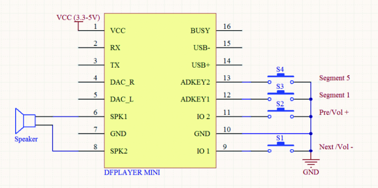
The module contains a MP3 decoder and a controller, capable of accessing the data contained in the SD-Card, via SPI: as the data stream is gradually read, the decoder converts it in audio format, that is then amplified by a small integrated amplifier, a mono one having a 3-watt bridge output (that is more than enough power to drive a loudspeaker capable of making its voice heard in the environment). If more power is required, please use the audio output (SPK + and –) in order to drive a power amplifier, to which to apply a cabinet.


