
[tps_header][/tps_header]
Today we are about to see how to build a DIY stopwatch just using Digital IC’s 4026 and 4017. The most highlighting feature about this project is the fact that it doesn’t use any MCU to do the job. Even though using an MCU will be a lot better option still this project will be a great DIY for those who love to play with Digital chips.
BLOCKS OF DIY STOPWATCH:
- Oscillator
- Display
OSCILLATOR BLOCK:
Oscillator provides the clock source for stopwatch we are about to build. The oscillator should provide an output clock frequency of about 1Hz. There are plenty of ways to do this but each method might differ in accuracy of output wave produced. Even a simple 555 timer can be used here, but temperature drift might affect the accuracy of output. The deviation of output might not be that big but its good to have it under consideration.
Crystal powered oscillator will be the perfect solution for this problem. We are not going to discuss the oscillator section briefly in this article since this 1 Hz oscillator circuit will do a pretty good job for our DIY stopwatch project. You can always use other 1Hz clock generator circuits rather than the crystal oscillators provided your application have some tolerance on the accuracy.
DISPLAY BLOCK:
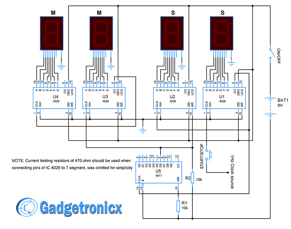 The display block uses 4 common cathode 7 segment for displaying the seconds and minutes of the count. The 7 segments marked as “S” for seconds and “M” for displaying minutes in the above circuit diagram. Use a 9v battery to power this block. Switch “ON/OFF” used to turn the counter ON or OFF. Use switch START/STOP to start and stop counting of Stopwatch.
Pages: 1 2


