
Not too long ago, I bought myself a USB Logic Analyzer from eBay at the cost of $9.50. This logic analyzer comes with 8 channels of digital input and able to support the sampling rate up to 24MHz. Why do you need a logic analyzer? This is very useful in debugging your programs whether they are sending/receiving the correct data or determining the timing of signals. If you are looking for this item in eBay, the item name is USB Logic Analyzer Device Set USB Cable 24MHz 8CH 24MHz for ARM FPGA. Before purchasing this low cost logic analyzer, I did some search from Google and found out that the logic analyzer is actually a clone of the Saleae logic analyzer.
This item comes in a package which includes the USB Logic Analyzer, USB cable and a 10 dupont line jumper. At the top of enclosure, there is a sticker which labelled Saleae logic, but of course this are not the original one. Besides that, there is also a pin labelling for the 10 pins Box header.
As mentioned previously, since this is a counterfeit of the original Saleae product, the seller does not provide any software tools to use it. Instead, they will redirect you to download the software from the Saleae website, detailed instructions will be shown later in this article.

Dupont line

USB Cable
I have listed down the specifications of this logic analyzer from the product page as below.

The supported sampling rate is capped at 24MHz and it can be adjusted in the software. They also clearly specified the acceptable input voltage range. For those who are not familiar with this specification, it is usually associated with most of the digital input device to state the input voltage level as shown in figure below.
In this case, any voltage falls between -0.5V to 0.8V is interpret as LOW and from 2V to 5.25V is interpret as HIGH. What about in between (0.8V to 2V)? There is no guarantee on how the device interpret it, it is in a INVALID state.

The enclosure of USB logic analyzer is simple that it can be easily opened. Due to curiosity, I have opened up the enclosure and not surprised that everything was fitted onto one single PCB.


Let us look into more details for the parts on the PCB. There are several surface mount ICs which are CY7C68013A – USB microcontroller from Cypress, 74HC245 – Octal bus transceiver and AT24C02B – Serial EEPROM.

CY7C68013A is an enhanced 8051 microprocessor with integrated USB 2.0 transceiver, operating at 3.3V with 5V tolerant inputs. It also has integrated I2C controller which can communicates with the external AT24C02B EEPROM chip. Referring to this blog, the EEPROM chip contains the Vendor ID and Product ID for the device to be identified as the Saleae USB Logic Analyzer.
The board features a green LED as the power on indicator and also a red LED as the Channel 1 input indicator. These two LEDs allows user to easily determine if the logic analyzer is working correctly.
Anyway, I don’t really like the dupont lines provided as I have to connect 10 individual jumper into the box header if I need to use it. I decided to make some modifications onto the jumper so that I can easily plug in and out from the logic analyzer. The solution is to make one end of the dupont line into a IDC female header.

IDC socket comes in three different parts

Clamp the socket to the dupont line

Another view

Clamped and cut the dupont line

Twist the dupont line and lock the final part

Taadaa!! IDC header to logic analyzer’s box header, done!
To use the logic analyzer, you need to download the software from Saleae download site. I am using the latest version of software, version 1.1.15. Installation is required before the USB logic analyzer can be used with host PC. After installation completed, plug in the USB logic analyzer to your host PC. Windows might attempt to search for update for the device driver, in this case, I just cancelled and let it search locally.
If everything works perfectly, when you launch the Saleae Logic software tool, you will notice [Connected] on the top bar. This shows that you are able to use your logic analyzer. On the other hand, if it is [Disconnected], you can only run in simulation mode.
On the first drop down menu, you can choose the number of samples to capture. Depending on the signals you are capturing and the rate of signal change, set the number of samples so you can capture all your desired data.

As I mentioned previously, you can select the sampling rate of the logic analyzer from the drop down menu.

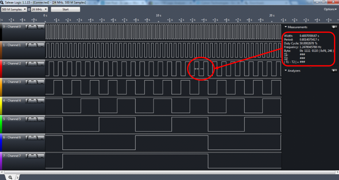
In order to test the functionality of this new USB logic analyzer, I quickly hook up an Arduino Pro Mini and program an 8-bit binary up counter. With this program, I am able to test all the 8 channels of logic analyzer. The user can set four different triggering method, rising edge, falling edge, signal HIGH or signal LOW for each channel. Next, click on the “Start” to begin acquiring signal.

Hardware setup
You can see from the figure below that the logic analyzer captures the signal perfectly.

Besides that, the software tool also allows measurement of signal such as pulse width, period, duty cycle, frequency, etc. Just hover your mouse over the signal, it will directly display the measurements on the upper right corner.
The logic analyzer can also be reprogrammed to use for the USBee instead of Saleae Logic. By tweaking the VID/PID in the EEPROM, it allows the logic analyzer to impersonate either Saleae or USBee. Read more on the reference at the end of article if you are interested.
Consideration whether to buy this logic analyzer, or not?
- Yes, if you are looking for a low cost logic analyzer which helps a lot in debugging your project. Being a hobbyist, sometimes we look for lower budget tools for our project, as we couldn’t afford buying high end tools at home.
- No, if you would like support on the original, which you are encouraged to. What I meant with supporting the original is to buy the logic analyzer from Saleae. They have developers that work hard to realize both the hardware and software for this. Their software is what makes it so good in using this. Furthermore, another feature that is only available from Saleae logic analyzer is the ability to sample analog input.
In a nutshell, this USB logic analyzer is a definitely a low cost solution for a hobbyist to have a logic analyzer at home. Hopefully this will be useful in debugging any projects in the future. Stay tuned for future projects on how I will be using this logic analyzer.
Reference

![]()


