How resistors are implemented in silicon
Resistors are a key component of analog chips. Unfortunately, resistors in ICs are very inaccurate; the resistances can vary by 50% from chip to chip. Thus, analog ICs are designed so only the ratio of resistors matters, not the absolute values, since the ratios remain nearly constant from chip to chip.
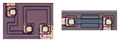
The photo below shows two resistors in the 741 op amp, formed using different techniques. The resistor on the left is formed from a meandering strip of P silicon, and is about 5KΩ. The resistor on the right is a pinch resistor and is about 50KΩ.
In the pinch resistor, a layer of N silicon on top makes the conductive region much thinner (i.e. pinches it). This allows a much higher resistance for a given size. Both resistors are at the same scale below, but the pinch resistor has ten times the resistance. The tradeoff is the pinch resistor is much less accurate.
How capacitors are implemented in silicon
The 741’s capacitor is essentially a large metal plate separated from the silicon by an insulating layer.
The main drawback of capacitors on ICs is they are physically very large. The 25pF capacitor in the 741 has a very small value but takes up a large fraction of the chip’s area.[5][6] You can see the capacitor in the middle of the die photo; it is the largest structure on the chip.
IC component: The current mirror
There are some subcircuits that are very common in analog ICs, but may seem mysterious at first. Before explaining the 741’s circuit, I’ll first give a brief overview of the current mirror and differential pair circuits.
If you’ve looked at analog IC block diagrams, you may have seen the above symbols for a current source and wondered what a current source is and why you’d use one. The idea of a current source is you start with one known current and then you can “clone” multiple copies of the current with a simple transistor circuit.
The following circuit shows how a current mirror is implemented.[7] A reference current passes through the transistor on the left. (In this case, the current is set by the resistor.) Since both transistors have the same emitter voltage and base voltage, they source the same current,[8] so the current on the right matches the reference current on the left.
A common use of a current mirror is to replace resistors. As explained earlier, resistors inside ICs are both inconveniently large and inaccurate. It saves space to use a current mirror instead of a resistor whenever possible.
[9]
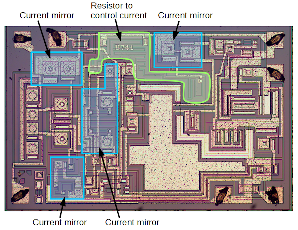
The diagram below shows that much of the 741 die is taken up by multiple current mirrors.
The large resistor snaking around the upper middle of the IC
controls the initial current. This current is then duplicated by multiple
current mirrors, providing controlled currents to various parts of the chip.
Using one large resistor and current mirrors is more compact and more accurate than using multiple large resistors.
The current mirror in the middle is slightly different; it provides an active load for the input stage, improving the performance.


