
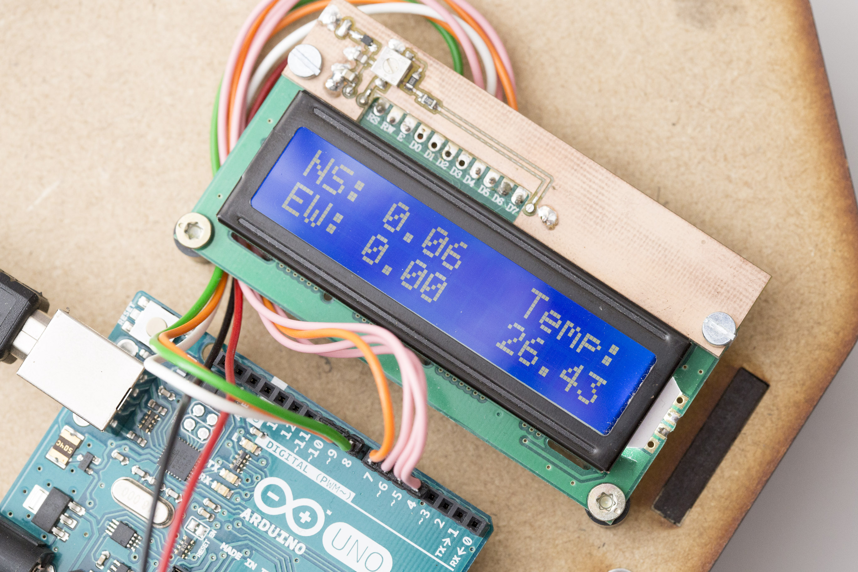
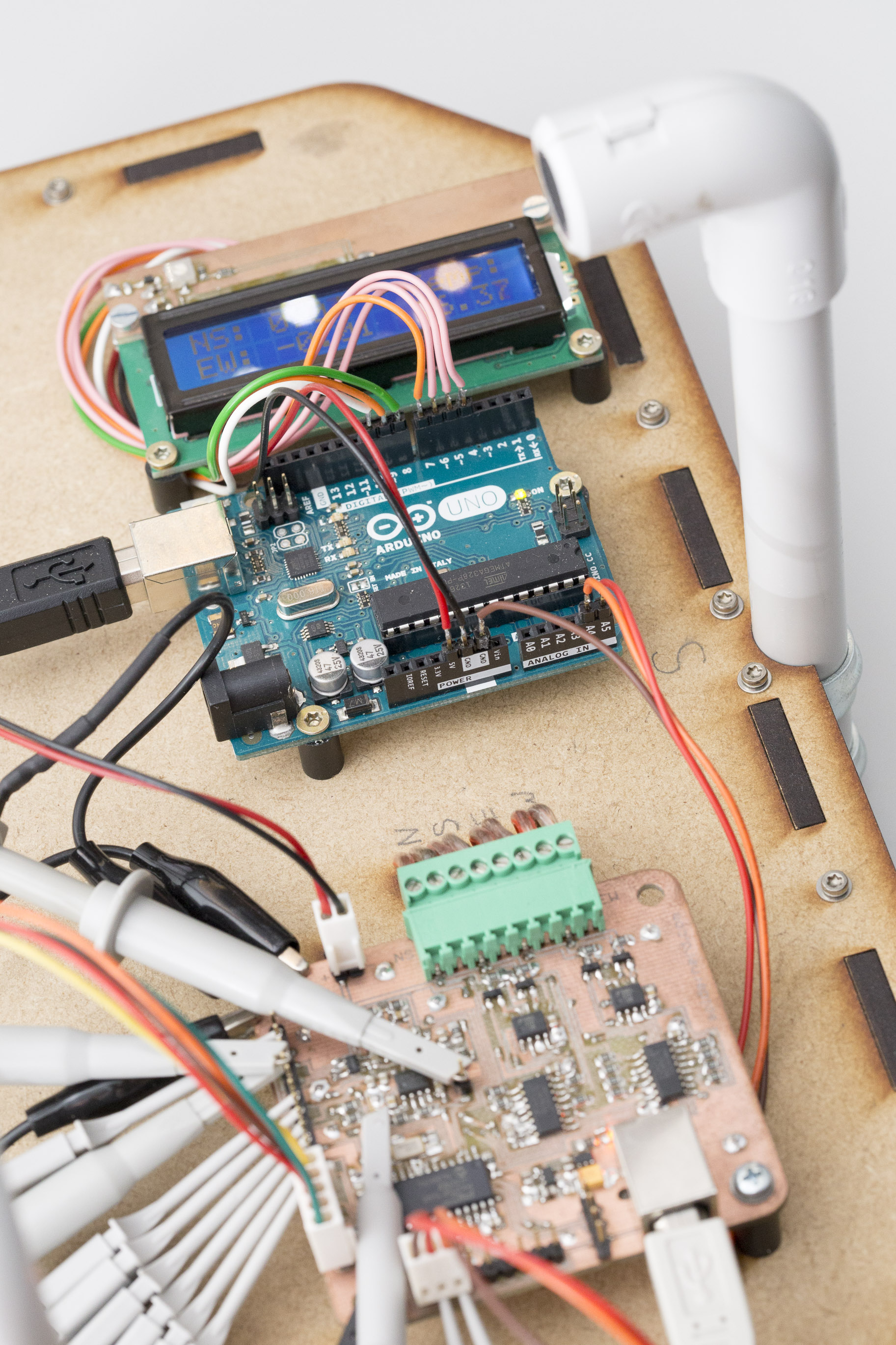
It’s been a long six weeks since my last post but that doesn’t mean that I haven’t done anything since. Among other things, I wrote some code to get the I2C interface working and hooked the anemometer up to an Arduino Uno with an LCD display attached. Apart from demonstrating the I2C interface this also nice for testing. For the first time I can see what this thing is measuring in real time without hooking it up to a PC over USB.
I2C Interfacing
But let’s look at the setup in some more detail. The PIC has a total of two I2C interfaces and I’ve made both of them accessible via the 100mil headers along the edges of the board. One of them is primarily intended for internal purposes like controlling the gain via the I2C digipot. The other one can then be used to interface to some external logic without having to worry about any internal communication. This external I2C interface also comes with 5V compatible pins which means we can interface to 5V devices like an Arduino without any further logic level translation. All we need is a pair of pull-up resistors pulling the SDA and SCL lines up to 5 volts. The Arduino’s Atmega328 already has built-in (weak) pull-up resistors so that’s not a problem. I didn’t think of interfacing to a 5V device when I designed the board and pulled the I2C signals to the anemometer’s 3.3V supply. So for proper 5V operation I’d have to unsolder the two 10k resistors. Luckily, 3.3 volts is enough to almost certainly be recognized as a logic high by the Arduino so the setup works anyway. But I will think about how to improve this in the next version. I might add a diode to allow the lines to be pulled higher than 3.3 volts.
The I2C interface can be configured to act as a master or as a slave device. For now I’ve only implemented slave mode so the wind meter behaves just like a I2C temperature sensor or external ADC. The Arduino acts as a master and asks the slave for its latest measurement every 250ms. The anemometer then returns 8 bytes of data consisting of 2 status bytes, north-south wind speed, east-west wind speed (both in mm/s as signed 16-bit integers) and temperature (0.01 degrees centigrade as signed 16-bit integer). It’s also possible to send data to the anemometer. That data is then saved to a buffer is otherwise ignored. In a future version of the software one might use this functionality to set the data format to wind speed and wind direction or to change the temperature unit to kelvin or fahrenheit.
It would not be difficult to implement master mode as well but so far I haven’t done it yet. A lot of code could be copied from the module communicating with the digipot where the PIC acts as a master. The anemometer could then push data to an external device whenever a new measurement becomes available. Definitely something I’d like to implement at some point but no priority right now.
Bug fixes
I’ve found (and fixed) a number of bugs while testing. Among other things, the axis and direction signals were not always properly set and so the measurements did not always correspond to the direction they should. So take with a grain of salt some of the test results reported earlier. Some of them were almost a bit too good to be true and this bug might have been the cause. I suspect I might have compared two successive measurements in the same direction when I actually wanted to compare measurements taken in opposite directions. But I’ve fixed the code and I’m confident that now all the directions are set and reported correctly.
Individual filter kernels

As can easily be seen from the scope screenshots above, the shape of the received signal varies quite a bit from transducer to transducer. Note that the amplifier gain is dynamically adjusted to make sure the peak amplitude is the same for all of them but the shape still differs quite substantially. So the kernel for the matched filter has to be some compromise to suit them all. I have now modified the software to use four individual kernels, one for each direction. This gives us the flexibility to calibrate the kernel to each transducer and so get more reliable results for the absolute phase.
Revised board

My main priority at the moment is to complete the revised version of the board and to order a small series of boards. Until recently I never ordered a board from a professional board house so there are quite a few things for me to learn. For the first time I have to worry about silk screen, for example. Or solder mask. On the other hand, a board house can do a lot of things I can’t. Plated-through holes for example. Or smaller vias. Or place vias under an IC. This means a lot more flexibility in my layout that I first have to get used to. But I’m making progress. I got a simple design of mine produced by dirtypcbs.com and got a batch of very usable boards. More on that in a future post.
Wind tunnel
If you’ve been following this project for a long time already you might remember my simplistic wind tunnel made of a 120mm brushless fan and a cardboard tube. I got a number of suggestions from you guys on how to build something better than that and I also found some useful material online. So I’ve started to build a much improved wind tunnel that will hopefully allow me to perform more meaningful tests. That’s also for one or more future posts.

Software ideas
I’ve also played around with some software ideas that I believe to have potential. One is dynamically adjusting the frequency. I’m now only working at the transducer’s nominal frequency of 40kHz. But the individual transducer’s resonance frequency might be somewhat different and might change with temperature or age. So I might try to adjust the frequency dynamically using some perturbation and observation algorithm.
I’m also thinking about measuring at two slightly different frequencies (say, 39.5kHz and 40.5kHz) and using the two phase shifts to figure out the absolute time-of-flight. I’ve given it a try and was not very successful but I haven’t given up on that idea yet.
So that’s it for now. The code for the Ultrasonic Anemometer as well as the Arduino are available for download. See the overview page for the respective links.


