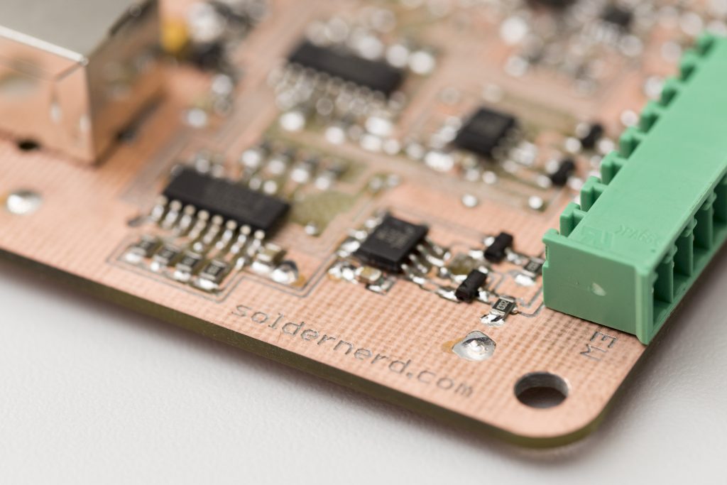
Last time I showed you the nice new hardware of the new standalone ultrasonic anemometer. But at that time I had hardly any software written for it so I couldn’t do much with its 32 bit microcontroller. So the last two or three weeks I spend lots of time writing code that I’d like to share with you today.
As I mentioned last time I worried most about getting the USB working properly. All the bit-fiddling with timers, PWM modules, input capture modules and the like can be time consuming and at time even frustrating. But I have all the confidence that I finally get what I aimed for. It might take a few nights digging through data sheets but in the end it will almost definitely work.
Now with USB I don’t quite have that level of confidence. The USB specification is quite overwhelming and there are almost countless registers to properly set and USB descriptors to specify. Without some sample code I’m pretty much lost I must admit.
Outdated Application Notes
So I was happy to see that Microchip has published a number of application notes and accompanying software. A handful of .h and .c files that you can include in your project, change some settings to suit your particular application and you’re ready to go. At least that’s what I thought.
All those application notes were published around 2008 and the code they are referring to is nowhere to be found nowadays. Aparently, Microchip has been quite pushy trying to get their PIC32 customers migrate to their new library or rather framework called Harmony. MPLAB no longer even includes the the PLIB peripheral library everyone has been using for decades. Microchip has depreciated it and while you can still download it they make very clear that Harmony is the library of the future.
On the road with MPLAB Harmony
So faced with few other alternatives I turned to the aforementioned Harmony library. It’s many hundred megabytes to download and takes up almost two gigabytes of disk space. It integrates nicely into MPLAB X and so I created a first project. You can graphically configure the clock and pin settings so I did that. Clicked on ‘create code’ and was nothing less than shocked by the code I got. Around a dozend source files scattered around in a dozend deeply nested folders and subfolders. And that was not yet it. Those files referenced dozends more files that came as part of harmony. It took me quite a while to just more or less figure out what the project was doing. And it didn’t do anything yet except setting some clock and port settings. Just a nightmare.
But I felt I had few other options so I continued with harmony anyway. And after a few hours I had an almost working USB device. It enumerated just fine but I couldn’t send any data from or to it. It took me more than a week to finally get it working. In the end it was just a single character: a 1 instead of a 2 in one of the configuration files. But until then I had spent a lot of time with that harmony code and was forced to read through a lot of its documentation which is worth thousands uppon thousands of pages of PDFs.
So USB was finally working and I had acquired some rudimentary understanding of MPLAB Harmony. I still hated the whole framework but I thought that I now understand it well enough to change the code to suit my taste. So I spent another few nights trying to do that until it dawned on me that this is leading nowhere. Fortunately, by that time I had read and learned some more about Harmony and was willing to give it another try working with it as opposed to against it. So for the last week or so I was doing that.
And while I still don’t love everyting about it I now feel comfortable working with that library. I’ve tried to follow its conventions and recommendations even where they didn’t make too much sense to me. I think this will make it much easier for others to work with my code and chances are that the conventions and recommendations will start to make more sense as I get more familiar with the framework. And its nice to know that I can integrate another module or migrate to another microcontroller without having to re-invent everything.
That was a long introduction but after all that pain the last few weeks I just had to write that down. Now to business.
USB
The anemometer inplements the USB HID (human interface device) class. While mainly aimed at devices such as mice and keyboards, this USB device sees a lot of use in applications that have nothing to do with human interaction. You can transfer up to 64 kbytes of data (64 bytes every millisecond) in each direction with guaranteed latency and that’s plenty for many applications. That data can be anything and in any format you like. And the good thing is that you don’t need to write your own drivers. You can free-ride on the device drivers that came with the operating system just like you don’t need to install a driver when you attach a new keyboard to your computer.
I’ve written a bit of code on top of the Harmony library to provide the main application with a simple to use interface. It nicely encapsulates the the USB logic and data and adds a bit of buffering functionality on top of that. It’s just two files: app_usb.h and app_usb.c in the app_usb subfolder. You can basically include them in your project and they handle all the USB stuff for you.
Once initialized, the necessary code runns inside an interrupt service routine (ISR) so the main application has nothing to worry about. All the USB data including the data buffers are private to the app_usb.c file. The app_usb.h defines just 8 simple, non-blocking functions:
- void app_usb_init(void);
- bool app_usb_isReady(void);
- uint8_t* app_usb_getReceiveBuffer(void);
- uint8_t app_usb_getReceiveBufferCount(void);
- uint8_t* app_usb_getTransmitBuffer(void);
- uint8_t app_usb_getTransmitBufferCount(void);
- void app_usb_freeReceiveBuffer(void);
- void app_usb_sendTransmitBuffer(void);
At system initialization you call app_usb_init(). But you can’t expect to have an USB connection. You need to check app_usb_isReady() every time. You never know if there is a USB cable plugged in and even if you had a connection that cable might be unplugged at any time. The module handles all that hot plugging/unplugging gracefully.
The module implements a circular buffer for both received packages (aka frames) and packages to be sent. Each package is 64 bytes in size and the ring buffers can be set at compile time but must be a power of 2. Currently the receive buffer consists of 4 frames and the transmit buffer of 8 frames.
The app_usb_getReceiveBufferCount() informs the caller how many new USB frames have been received if any. app_usb_getReceiveBuffer() then returns a handle to the first received frame. FIFO – First In First Out. Once the frame is no longer needed the application calls app_usb_freeReceiveBuffer() and the buffer can be re-used.
Sending data works similarly simple. app_usb_getTransmitBufferCount() returns the number of transmit buffers currently in use. If this number is smaller than then number of buffers then more data transmissions can be scheduled. Get a handle to then next buffer by calling app_usb_getTransmitBuffer(), write the data to be sent to the buffer and then call app_usb_sendTransmitBuffer().
Taking measurements
This way the main application can focus on more interesting tasks such as measuring wind speed and direction. The first task for doing so is sending some pulses.
If you’ve alredy followed this project for a while you are probably familiar with the kind of screenshot above. Bursts of a PWM signal at 40kHz (SIGNAL, red) are sent trough ultrasonic transducers. Note that the signal is now active-low (i.e. inverted) since the mosfet drivers used to drive the transducers are themselfs inverting.
As before, the DIRECTION and AXIS signal determine which transducer is transmitting and receving. The SCLK and MOSI signals are just used for debugging purposes for now. They indicate when an ISR is running which helps a lot since in this example ALL the code is running inside an ISR.

As you can see above, the AXIS and DIRECTION signals are set a few microseconds before we start sending pulses. The first edge of the burst occurs when the 32 bit-timer (consisting of the 16-bit timers TMR2 and TMR3) is cleared. This is the point in time all our measurements are referenced to. The timer runs at the full CPU clock of 48Mhz so the resolution is about 20.8 nanoseconds.
Output Compare module 2 (OC2) handles the PWM pulses. Currently each burst consists of 12 pulses. At 48MHz a full wave equals 1200 clock cycles as opposed to 400 on the Arduino previously used. Note that the frequency of the pulses is precisely 40kHz as expected and that very little time is spend in ISRs despite the unoptimized C code.
The timer overflows precisely 512 times per second so each measurement takes a little less than 2 milliseconds. Output compare module 1 (OC1) can be used to generate an interrupt at any time during that interval. Currently it does three things: It takes care of the AXIS and DIRECTION signals which are set just shortly before the timer overflows. It also triggers the measurements of the zero-crossings and cancels them if they don’t complete withing reasonable time.
The input capture module 4 (IC4) captures the zero-crossings of the received and amplified signal. The board contains a high speed comparator to detect these events so the microcontroller only needs to measure the precise time whn they occur. The IC4 module has an internal buffer so we don’t need to generate an interrupt after every capture. I’ve currently set things up so that an interrupt occurs after 4 values have been captured up to a total of 32 measurements.
Commicating the results over USB
In order to find the wind speed and direction we need to somehow identify the peak in the received signal which is where the ADC comes in. But I think this is enough for now and I instead show you how the measurements taken so far can be sent to a PC via USB.
The board doesn’t have any display or anything to communicate with a human. There’s not even a status LED we could blink. That would have been nice but there are just not enough I/O pins unfortunately. So connecting the board to a PC via USB is a straight-forward way of communicating with this device. Actually, USB will be the main testing and debugging tool during development. The in-circuit debugger isn’t very useful in this application since the measurements have to happen in real time. Setting breakpoints will just mess things up.That’s why I insisted to get USB working first.
I’ve downloaded a simple terminal called YAT (yet another termial) that allows me to easily talk to the anemometer board. The anemometer looks at the first character in any message sent from the host and then decides what to do. So far I’ve implemented:
- ‘T’: Return the current value of the 32-bit timer
- ‘Z’: Return axis (0/1), direction(0/1), measurement count (0-31) values as well as the results of the first 9 zero-crossing measurements
- Anything else: Echo back the received string
Here’s what my chat with the Standalone Ultrasonic Anemomete looked like.
Of course, the measurement is far from complete at this stage but I think this is a nice foundation to build uppon. The code is quite clean for this early stage of development and being able to communicate with the device in real-time over USB is really a great advantage.
The software can be downloaded on the project over view page and as always I appreciate any feedback.
The next post on this project can be found here.


