
In this article, I’ll present you ‘the beast’: a cortex M4-based platform that has plenty of communication interfaces and to which you can connect a lot of different peripherals:
Preface
Before starting this project description, let me first say that I’ve already guessed that many of you might find this board overkill, or maybe think that I could have done the same with an Arduino/RPi/Beaglebone/PC/{insert dev. platform here} and (a lot of) shields. Even more people would say that I should have used an embedded operating system.
Well, I chose to design my own board and skip the OS for a few reasons:
– It’s fun to design a 4 layers board with so ‘many’ components 😀
– I always wanted to create a platform with USB/ETH/BT/Audio/uSD/…
– For this particular project, I had very small space available to put the electronics
– I enjoy low-level programming, and believe you can get better performances without an OS
Project specifications
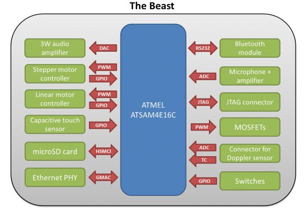
I only had two months (nights and weekends) to design this platform for my father’s project, which required:
– a small audio amplifier
– capacitive touch sensors
– stepper motors controllers
– a microphone and its amplifier
– MOSFETs to control LED strings
– connectivity for my doppler motion sensor
– a microSD card connector for data storage
– a linear motor controller with protection functions
– Ethernet connectivity to fetch data from the Internet
– a battery retainer to provide backup power to the microcontroller
– Bluetooth connectivity to scan available devices with their RSSI
– a USB port for communications and access to the microSD card
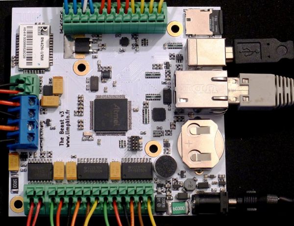
As shown in the title picture, the board is full of terminal blocks so you don’t need to solder anything to connect your motors/LEDs/touch pads/… The chosen microcontroller is the Cortex M4 based ATSAM4E16C from Atmel, which has 1Mbyte of flash and 128Kbytes of SRAM. It also includes plenty of peripherals such as a Real Time Clock (RTC), a USB controller, an Ethernet MAC, an Analog to Digital Converter (ADC) and a Digital to Analog Converter (DAC). As a reminder, the Cortex M4 allows Digital Signal Processing (DSP) based instructions so doing some maths (FFTs and stuff) on the platform should be a piece of cake.
Demonstration video
To get your interest in the platform going, I made a simple demonstration video:
Power related components
Rather than displaying the complete schematics at once, I’ll explain each block separately.

Let’s start with the power input (lower left of the picture). 12V @ 3A is applied through a standard 2.1/5.5mm barrel connector (CON2). The board is protected by a TVS diode (D2), a resettable fuse (F1) and a ferrite (FB1). The 3.3V provided to the microcontroller and its peripherals is generated by a a step-down buck regulator (U1) cascaded with a LDO (U5). Using the LDO allows us to have a cleaner 3.3V than if we were just using the step-down. This may not be required if you aren’t planning to use the ADC.
The annoying thing with the SAM4E is that it doesn’t have a dedicated backup power supply input pin. So in the schematics, there are two +3.3V rails (3.3V and Vcc). The former is dedicated to the microcontroller while the latter powers the other components and is only activated (by Q1) if +12V is connected to the board. In case the +12V drops and a battery is present on the board (BT1), a (small) voltage would still power the microcontroller (which will automatically go into sleep mode). Instead of doing like I did, most hobbyists would go for a simple 2 diodes setup, but in this case the voltage on the 3.3V rail would drop depending on the consumed current.
Backup power is only used to keep the RTC running and store a few values in the microcontroller’s backup registers. When the +12V is removed, power is consumed by the ATSAM4E but also by the LDO (back powering) and the D5 diode (leakage). From the few measurements I made, the longest the board can stay in deep sleep mode with the CR2032 battery is around 1 month and a half. Again, this board is not meant to stay unpowered for long periods of time.
It is important to mention that D3 has been chosen so the reverse voltage leakage current (the current going from the 3.3V to the battery) is very small (less than 0.01uA) so the battery won’t blow up.
USB and the microSD card
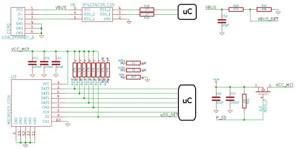
The USB lines are protected against ESD surges by U6 and the USB plugged event is detected by monitoring the USB 5V rail. Power to the uSD card can be (de)activated using the PMOSFET Q2. This came handy when developing on the platform as many SD commands are interrupted between debugging sessions, leaving the SD card in an unknown state. A clean power cycle solves all these problems.
Communications between the microcontroller and the uSD are done using the ATSAM4E High Speed MultiMedia Card Interface (HSMCI), which uses a 4 bits bus with command and clock signals.
Ethernet
Advertisement1
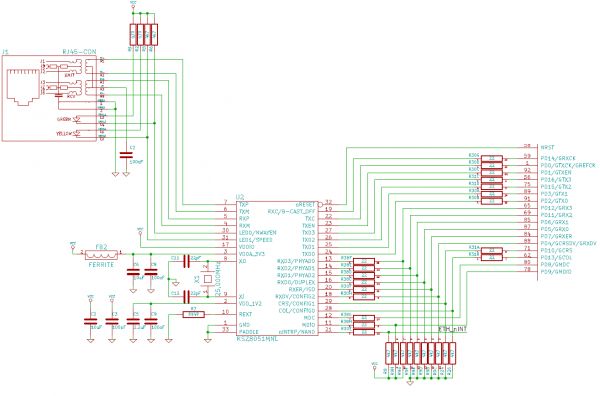
The ATSAM4E Ethernet MAC needs an Ethernet physical transceiver (PHY) to generate / decode signals coming from the Ethernet port. I had the good surprise to discover that the PHY supported by the Atmel ASF was one of the cheapest that could be found on digikey 🙂 . The 22 ohms resistors put in series in the data/clock lines are meant to suppress reflections that may occur in high speed buses. Pull-ups/pull-downs set default parameters of the KSZ8051.
Audio
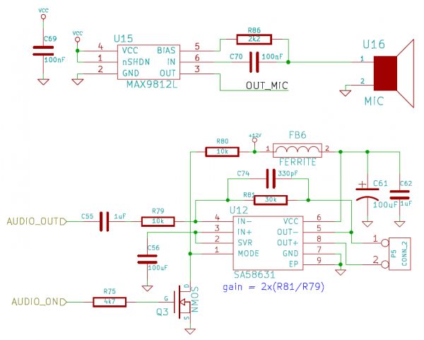
The sound coming from the on-board microphone is amplified by 20dB by the MAX9812 and fed to the ATSAM4E ADC. Only one DAC channel is sent to the SA58631 3W audio amplifier. C55, R79, R81 and C74 form a band pass filter between 16Hz and 16KHz. This is obviously not a high-end audio amplifier but it is good enough to listen to some music. The amplifier gain is fixed so setting the volume should be implemented in the firmware, which is not a problem for the Cortex M4. The ‘audio_on’ signal (de)activates the amplifier.
Motor controllers
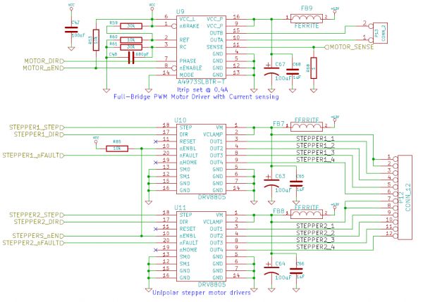
The A4973 (U9) is a full-bridge PWM motor driver. It allows us to control the motor in both directions and will limit the current in case the motor is stalled. We can also control the motor speed by feeding a PWM signal to the enable pin. The current at which the controller will enter its ‘current regulation mode’ can be set using a few resistors, as well as the current given to the motor during this mode. The voltage present on the current sense resistor is fed to the ATSAM4E ADC for monitoring.
Unipolar stepper motor drivers (U10 & U11) control the steppers connected to the board. The microcontroller only needs to send them direction, enable and step pulse signals. The controllers can detect faulty connections, and you have to keep in mind that enabling them will ‘block’ the stepper shaft (see how a stepper controller works here).
Capacitive touch sensing
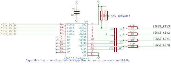
I promise, things are starting to get easier to understand from here 😉 . The AT42QT1040 from Atmel is a nice chip which will automatically detect changes in capacitance of its inputs. The two pull-up resistors adjust its parameters, here Adjacent Key Suppression (AKS) and fast mode are activated. Touch sensitivity can be adjusted by changing the 4 capacitors values.
Bluetooth
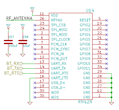
The RN42 is a Bluetooth to serial bridge. This particular chip was picked because it is the only one that gives the devices’ Received Signal Strength Indicator (RSSI) when performing a scan. This was used to detect if a particular phone was present in the platform proximity. This feature was only implemented in recent firmware versions, so you have to directly order from Microchip rather than using Digikey (yes… this happened). The antenna is a simple trace on the PCB, its design was given by an application note.
MOSFETs
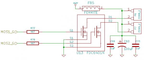
Not much to see here… just mosfets for the LEDs 😉 .
The Firmware
Dealing with the Atmel Software Framework (ASF) is long and annoying. Libraries’ documentation is hard to find, not clear and you often have to resort to look at the code to have a sense of what it is doing. Implementing a composite CDC/MSC with access to the uSD card was done by looking at all the examples provided by Atmel but also by spending quite some time looking at all the header files. However, once you get the hang of it development will become quicker.
I particularly enjoyed creating a DHCP and NTP client from scratch (note to self: implement the DHCP re-request once i have the time). I’d also like to create an SDcard bootloader but I’m too busy for that. Therefore, I’ll send one of the prototype boards to the one person that’d like to make it (contact me via the message form).
Conclusion
I nearly missed the summer because of this d*mn project but I’d like to think it was worth it.
This ‘beast’ is quite versatile so perhaps it might interest other persons. I therefore made a fundraiser on Tindie but as you’ll see the board is a bit expensive even if the BoM cost for 100 prototypes is around 63USD. As usual, I decided to not make any money out of the fundraiser. Here are all the files in case you’d like to modify my work:
BoM Beast Kicad files schematics(PDF) gerbers test firmware
I’d like to apologize in advance for my code. As I said, I only had two months to make this project so even if most functions are documented there may still be a few bugs 🙂 .


