The primary: chopping up the power
The primary circuit is the heart of the charger.
It takes the high voltage DC from the PFC circuit, chops it up and feeds it into the transformer to generate the charger’s low-voltage output (16.5-18.5 volts).
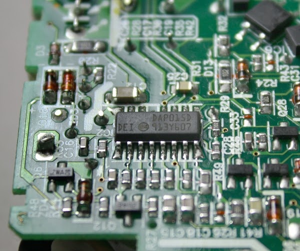
The charger uses an advanced design called a resonant controller, which lets the system operate at a very high frequency, up to 500 kilohertz.
The higher frequency permits smaller components to be used for a more compact charger. The chip below controls the switching power supply.[7]
The two drive transistors (in the overview diagram) alternately switch on and off to chop up the input voltage. The transformer and capacitor resonate at this frequency, smoothing the chopped-up input into a sine wave.
The secondary: smooth, clean power output
The secondary side of the circuit generates the output of the charger.
The secondary receives power from the transformer and converts it DC with diodes. The filter capacitors smooth out the power, which leaves the charger through the output cable.
The most important role of the secondary is to keep the dangerous high voltages in the rest of the charger away from the output, to avoid potentially fatal shocks.
The isolation boundary marked in red on the earlier diagram indicates the separation between the high-voltage primary and the low-voltage secondary. The two sides are separated by a distance of about 6 mm, and only special components can cross this boundary.
The transformer safely transmits power between the primary and the secondary by using magnetic fields instead of a direct electrical connection.
The coils of wire inside the transformer are triple-insulated for safety.
Cheap counterfeit chargers usually skimp on the insulation, posing a safety hazard.
The optoisolator uses an internal beam of light to transmit a feedback signal between the secondary and primary. The control chip on the primary side uses this feedback signal to adjust the switching frequency to keep the output voltage stable.
A powerful microprocessor in your charger?
One unexpected component is a tiny circuit board with a microcontroller, which can be seen above.
This 16-bit processor constantly monitors the charger’s voltage and current.
It enables the output when the charger is connected to a Macbook, disables the output when the charger is disconnected, and shuts the charger off if there is a problem.
This processor is a Texas Instruments MSP430
microcontroller,
roughly as powerful as the processor inside the original Macintosh.[8]
The square orange pads on the right are used to program software into the chip’s flash memory during manufacturing.[9]
The three-pin chip on the left (IC202) reduces the charger’s 16.5 volts to the 3.3 volts required by the processor.[10]


