
Based on Arduino, it performs electronic light games by piloting a LED matrix thanks to a special multiplexing mode.
In the “fast paced world” we live, moments when we can do whatever we want are rare and we have to cut them out from our routine, by skillfully balancing between the busy schedule of the day. We are always so in a hurry that the only relaxing moments we have, could be the public transportation waiting time, or when we are queuing in a bank or at the post office. In these moments, people read a book, someone checks the latest Facebook or WhatsApp notifications, someone plays with the smartphone, and someone listens to music and meanwhile fiddle with keys or maybe with a click pen.
From this shared desire to have a diversion in boring moments, we had the idea of creating something on purpose – something electronic -: a little game, integrated into an everyday object.
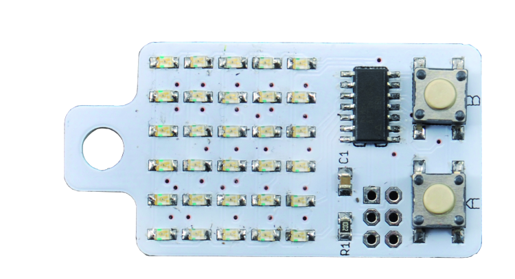
Thus we designed a LED matrix “display” controlled by a small microcontroller, compatible with Arduino and integrated in a PCB of the shape and size of a key ring.
After taking shape, our idea caught a name as well: KeyChainino. The name is already indicative of what the circuit is: a keychain based on Arduino. It is actually a programmable electronic keychain, where everyone can create a game or a light game.
KeyChainino is made by a 6×5 LED matrix and two buttons controlled by the small ATTINY84A, a SMD Atmel 8-bit microcontroller, which has only 14 pins so it is sufficiently miniaturized for our purposes.
To drive all the LEDs, however, we would need almost all of the I/O pins available on the micro and we need to control the buttons too: we have solved this problem with a trick we will describe in a moment, by analyzing the electronic circuitry behind the project.
Wiring diagram
Everything is controlled by the Atmel microcontroller, that we see (in the circuit diagram) surrounded by a LED matrix connected in an original way: not the traditional rows and columns scheme, but LEDs connected in cascade between two pins of the microcontroller.
This particular configuration, which will be explained in the next paragraphs, allows with only 14 pins to control 30 LEDs, thanks to a technique known as Charlieplexing; with the traditional multiplex the control of 30 diodes would have required a 5×6 matrix, so 5 + 6 = 11 pins.
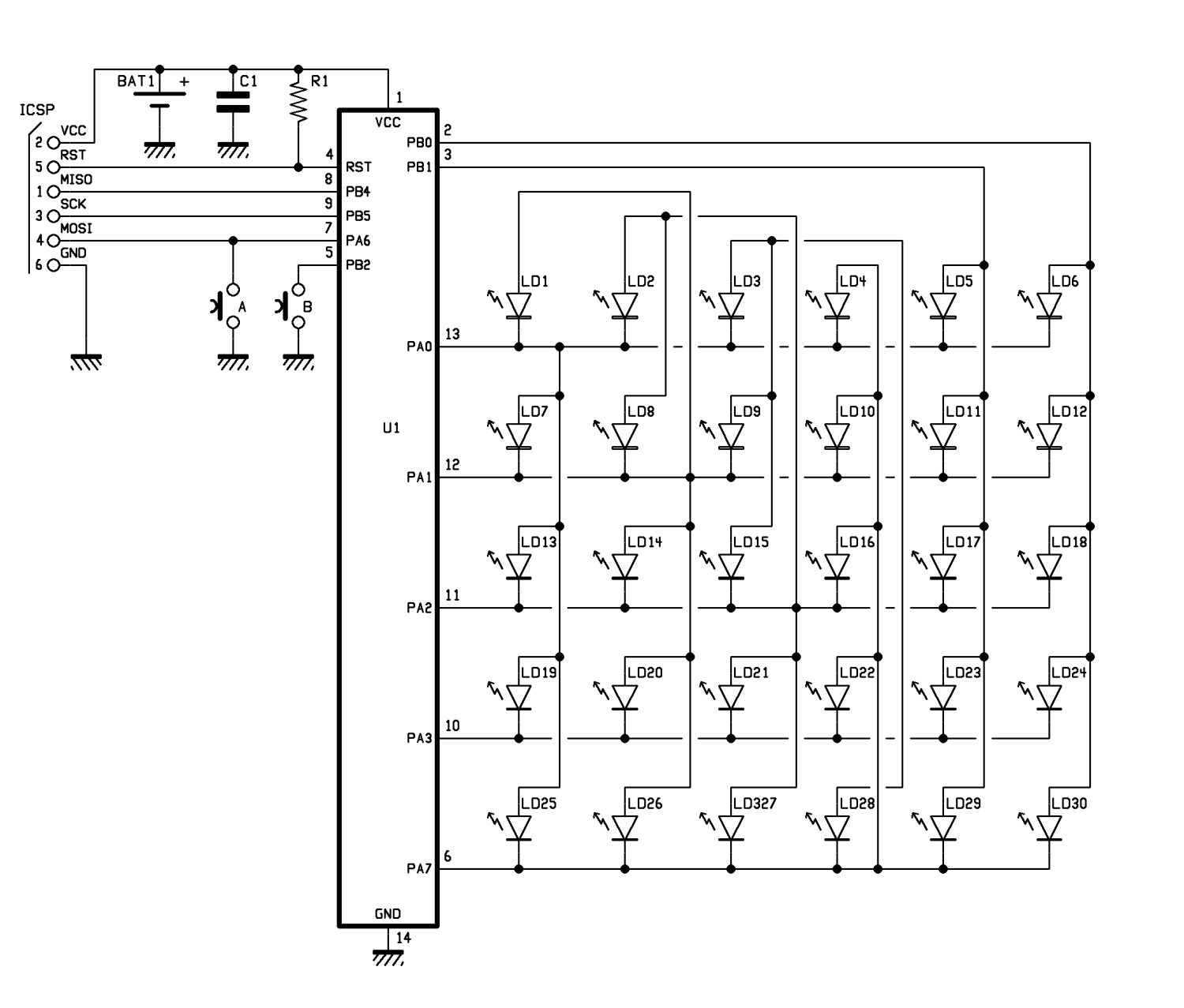
Here, we need seven only.
The Micro works with the internal oscillator and that’s why you don’t see any other timing component such as quartz or capacitors in the circuitry; this helps the maximum circuit simplification, which is reduced to the microcontroller, the LED array, the pull-up resistance applied to the RST pin (which in “rest” state is in high level – this is the normal micro working mode – but its state can be switched by the developer through the ICSP connector) and to the power filter capacitor, which in this case is only 3 volts and is ensured by a CR2032 button cell.
The buttons connected to PA6 (which is the MOSI data line, for the developer) and PB2 lines manage the various game features; the two I/Os are connected to a microcontroller internal pull-up resistor which is activated by the firmware in the I/O initialization phase.
Since the microcontroller power supply line is connected to the ICSP connector Vpp pin, when you program the ATTINY84A you must remove the battery from its housing, since the voltage provided by the programmer is definitely higher.
That said, let’s focus on the “juicy” part of this circuit, i.e. the Charlieplexing: this technique, which is a multiplex scheme, is based on the fact that a certain LED of the array works only when the voltage at its ends is enough to polarize it directly. Playing on a specific connection and placing the LEDs as you see in the wiring diagram, since the microcontroller pins can have three logic states (HIGH, LOW, high impedance / three-state) you can control multiple LEDs with each I/O.
The “Three-state” status is achieved when we set the pin as a digital input, since the I/O line assumes a high impedance state, which greatly limits current (resulting nearly open).
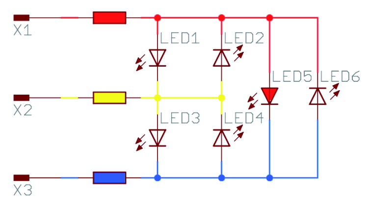
To make you understand how the Charlieplexing works, let’s look at the diagram in figure, that allows to drive six LEDs with only three microcontroller lines. Assuming that X1, X2 and X3 are the three Arduino pins involved, let’s try to light the LED1 on.
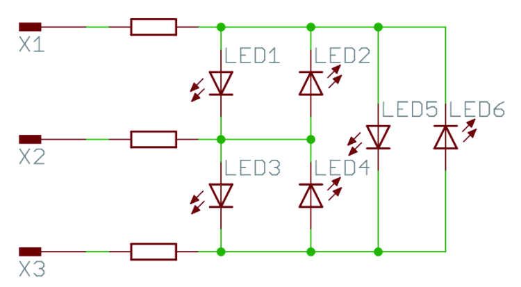
To do so, in Arduino, let’s configure X1 and X2 -which are connected to LED1- as OUTPUT; set X1 to logic level HIGH and X2 to logic level LOW. As for X3, we configure it as INPUT:
pinMode(X1, OUTPUT);
pinMode(X2, OUTPUT);
pinMode(X3, INPUT); //Three-State
digitalWrite(X1, HIGH);
digitalWrite(X2, LOW);
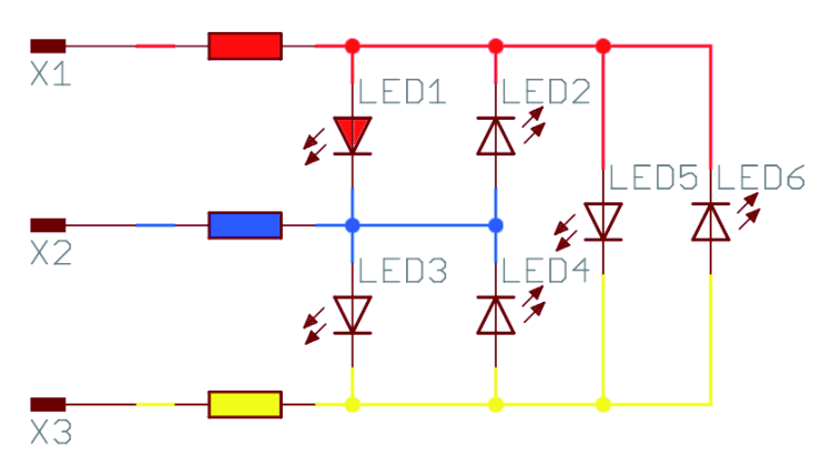
In this way the LED1 lights up, while other LEDs remain off.
Note that LED2, which is connected to the same LED1 pin, does not turn on because it is connected in “anti-parallel” respect to LED1, so you can turn it on by reverting the polarity (this turns LED1 off).
Now, to turn off LED 1, we just set all the pins in Three-State, so configure them as INPUT:
pinMode(X1, INPUT);
pinMode(X2, INPUT);
pinMode(X3, INPUT);
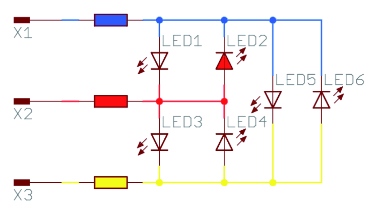
If we want to turn LED 2 on, for example, you just configure the connected pins (X2 and X1) to OUTPUT, X2 in HIGH and X1 in LOW state. X3 is left in in three-state condition:
pinMode(X1, OUTPUT);
pinMode(X2, OUTPUT);
pinMode(X3, INPUT); //Three State
digitalWrite(X1, LOW);
digitalWrite(X2, HIGH);
In this configuration, the current flows from X2 to X1 pins crossing LED2 and polarizing it directly. Instead the X3 pin does not interfere, since it is configured as INPUT.
Let us now turn the LED5 on: to do this, we must set X1 and X3 to OUTPUT, then X1 to HIGH and X3 to LOW while X2 is a INPUT (three state):
pinMode(X1, OUTPUT);
pinMode(X2, INPUT); //Three State
pinMode(X3, OUTPUT);
digitalWrite(X1, HIGH);
digitalWrite(X3, LOW);
Now the LED 5 is turned on. We wonder why LED 1 and LED 3 are not on, even if the voltage across them is polarized correctly; Well, the fact is that these two LEDs are connected in series and then, to be turned on, the microcontroller should provide twice the voltage requested by a single LED. Since the microcontroller always provides the same output voltage, the two LEDs are off in this configuration: that’s why we are using this wiring scheme.
Now that we have figured out how to turn on many LEDs with few pins, we must consider a Charlieplexing limitation: with this specific LED driving technique, you can turn on a single LED at a time. This limits us a lot: in fact, how can we “draw” a smile, for example, on the KeyChainino LED display?
Well, what is feasible because what we truly need is to see the LEDs lit at the same time, not to turn LEDs on at the same time: it is a subtle difference – a word pun, if you like – but it explains perfectly the POV – an acronym for “persistence of vision” – concept. To understand it, we have to know that our eye cannot distinguish between images that follow one another over a certain frequency, that science has demonstrated to be 24 frames per second; this is for both the persistence of the retina (i.e. the time taken by the rods and cones in the human eye to adapt to light variations) and the speed of brain processing.
It follows that if we turn a LED on and off much faster than the human eye can perceive, we cannot perceive how we are driving the LED matrix but we see the final result: KeyChainino LEDs displaying a smile.
This is exactly what we do with our application. LEDs are pulsing very quickly (more than 24Hz) and we perceive them as “always on” even if it is not the real behavior.
We combined this technique with the Charlieplexing, so by switching LEDs on and off at about 60Hz refresh frequency, we can display complex images: our eyes will be deceived.
The real problem is to make the LED array management easy, without worrying about their connection scheme and high refresh rate. So we have created a function that, through the use of timer interrupts, updates the LEDs status in “background”.
What we should do in the sketch is to change only the LED value to be switched on, in the multi-dimensional vector “matrixState”.
For example, if we want to turn on the LED in position [Y] [X], we just write:
matrixState [Y] [X] = 1;
To turn it off, simply set the value back to 0. In this way we can turn on and off at the same time all of the 6×5 LED matrix without having to worry about anything. Our function, associated with the timer interrupt number 1, will check which LEDs it must turn on and configures the right pins according to the specific LED connections.
Another advantage of Charlieplexing is the low power consumption it can grant: that’s why we implemented it in KeyChainino, which is powered by a 225mAh 3V CR2032 battery.
Let’s explain it clearly.
Power consumption is a key factor because if we turn all 30 LEDs on in a traditional way, each led has an estimated consumption of about 10mA, so we would have a 30x10mA= 300mA current. If we assume that the battery has a drain current enough to light all the led up, it would run out very quickly (225/300=0,75 hours, that is 45 minutes).
With the Charlieplexing, since we power up a LED at a time, the total consumption is always 10mA. Moreover, LEDs are on for only 1/30th of a second, that is like we are driving them with a 3.33% duty cycle PWM technique. The battery can keep the display on for about 225mAh/10mA=22.5 hours, but we have to take into account that the fast switching time is actually reducing the light intensity as well.
Another aspect to consider is that Charlieplexing requires a LED current limiting resistor (put in series …). Normally such resistance is calculated by dividing the difference between the voltage supplied to the resistance-diode couple and the diode only voltage drop, for the LED direct current.
Then since each LED is connected to two pins, the calculated resistance must be divided by two and connected in series to each respective microcontroller pin. In this way, each LED is always connected in series between two resistors whose sum is the one required for optimum LED operation.
This applies in general for Charlieplexing drivers but in some conditions you can avoid using the limiting resistance. One of this cases is ours, since the LED working voltage is very close to the battery voltage and the MOSFETs voltage drop can easily compensate the behavior of the resistance. That’s why in KeyChainino we didn’t put any limiting resistance.
Another condition that supports our decision to omit it is that LED are on for a very short time, thus they can tolerate a slight overvoltage without being damaged.
If you’re using in your custom project a power supply voltage higher that 3V, you should consider putting the limiting resistances in the PCB.
KeyChainino is therefore an excellent tool to learn the surprising Charlieplexing technique, to find out how you should use interrupts and learn how to manage the energy saving; all in a single and very common object, always with your keys!
Creating games for KeyChainino is very simple: starting from the basic sketches you can download from GitHub: https://github.com/alessandromatera/KeyChainino/blob/master/Sketch/KeyChainino_basic/KeyChainino_basic.ino
Then you can follow the tutorials found on the project web site, created by the author:
http://www.keychainino.com/tutorial-how-to-make-the-walled-game-step step-by-part-1 /.
Or you can simply use one of the various games developed by the project author or by other users available at:
www.keychainino.com/keychainino-sketches/ and modify their sketches if you like.
The main referring point for all KeyChainino applications it the official project website, constantly updated:
CIRCUITRY IMPLEMENTATION
Let’s move from theory to practice now and see how to build this gadget: to contain the circuit size we used SMD components and a plated holes,double sided PCB and bare copper wiring. You can download the PCB blueprint at openstore, together with the other project files.
The board assembly thus requires the necessary equipment (a 20 W fine tip welder, the 0.5 mm diameter soldering wire, the medium density flux paste, a magnifying glass and tweezers to position smaller chips), as well as a lot of patience and a steady hand.
Start by placing the microcontroller first, well centered in its socket pitches, and soldering two corner pins to fix it; then proceed to weld pins alternatively one for side, after having them coated with the flux paste to prevent the solder from sticking between two legs, short-circuiting them. In this operation, help you with the magnifying glass, because the pin pitch is very small and it is easy to make short circuits. Once the microcontroller is fixed, place the smallest components such as resistors and capacitors, then the LEDs, the quartz, the capacitor and the buttons. Complete the installation with the battery holder and the ICSP connector, which is a double male strip 2.54mm pitch 3-pole connector, to be removed after the in-circuit programming of the microcontroller: that connector is taking too much space for a keychain.
Once done and programmed, KeyChainino must be put in a plastic container (transparent on the LED matrix side) according to your taste; You can also evaluate the possibility to cover the LED side with a transparent resin (a few hands of polyurethane paint, for example) and the back side with a lid, always in insulating material.
Video
From openstore
KeyChainino – programmable keychain


