
Most of the alpha numeric LCD like 16×2 char or 16×4 char have ability to generate few custom characters. in this example i will show you how to make and display these custom characters on a 16×2 char lcd with Hitachi HD44780 lcd controller.
HD44780 LCD can have upto 8 custom characters.
THEORY FOR CUSTOM CHARACTER GENERATION
the basic technology of lcd based on 3 type of memory
CG ROM : this the memory which holds the permanent fonts you call to be displayed . this holds the pattern for every single character of predefined lcd font. and you call the content of this memory by the placing corresponding ascii value on the lcd port . like for retrieval of ‘A’ you have to send the ascii value of ‘A’ which is 0x41 to the lcd. CGROM can also be seen as computer hard drive from where you load your required program into ram to start working. but it is not modify-able because it’s rom.
DD RAM : DDRAM is the memory which holds only those characters which are currently on the screen . means if there is a message is currently being displayed on the screen then it has to be on the DDRAM
for example if you want to display “hello” on the screen then you have load pattern of h from the CG ROM TO DD RAM then do the same for ‘e’ ,’l’ ,’l’ and ‘o’.
Advertisement1


for example if you want to display “hello” on the screen then you have load pattern of h from the CG ROM TO DD RAM then do the same for ‘e’ ,’l’ ,’l’ and ‘o’.
the address of cg ram is totally depends on the size of the lcd like for
16 x 2 LCD Row1 0x80 0x81 0x82 0x83 0x84 0x85 0x86 through 0x8F
Row2 0xCO 0xC1 0xC2 0xC3 0xC4 0xC5 0xC6 through 0xCF
20 x 1 LCD Row1 0x80 0x81 0x82 0x83 through 0x93
20 x 2 LCD Row1 0x80 0x81 0x82 0x83 through 0x93
Row2 0xCO 0xC1 0xC2 0xC3 through 0xD3
20 x 4 LCD Row1 0x80 0x81 0x82 0x83 through 0x93
Row2 0xCO 0xC1 0xC2 0xC3 through 0xD3
Row3 0x94 0x95 0x96 0x97 through 0xA7
Row4 0xD4 0xD5 0xD6 0xD7 through 0xE7
40 x 2 L CD Row1 0x80 0x81 0x82 0x83 through 0xA7
Row2 0xCO 0xC1 0xC2 0xC3 through 0xE7
CG RAM : this memory works same as CG ROM but as this is ram we can modify it’s content any time . so this is the place where we have to first store our custom character pattern. then that pattern can be sent to display.
the HD44780 has total 8 CG RAM memory location . so we can generate only up to 8 custom characters . but you can always change the content of CG RAM on the fly to generate new characters .
the addresses of 8 CG RAM location goes from 0x00 to 0x07.
WHEN Ever we want something of these fonts to be displayed on the screen we write them to the DD RAM
NOW QUESTION IS
HOW TO POINT TO CG RAM MEMORY LOCATION instead off DD RAM, so that we can write something ?
the answer is quite simple The HD44780 provide a dedicated command to set writing pointer to CG RAM
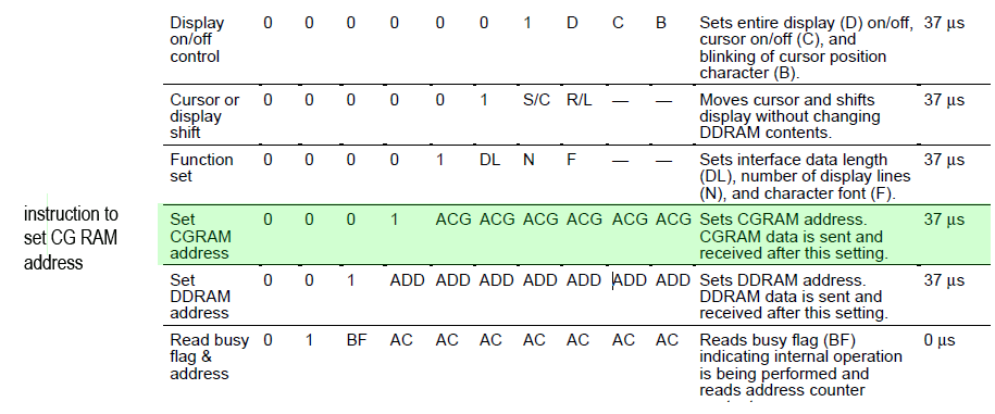
for example if you want to write you first custom character to 0x00 CG RAM location then you have to send lcd a command
lcdCmd(0x40);
after this now you are ready to send data to CG RAM location 0x00.
after sending the whole pattern for location 0x00 the location pointer will auto increase to 0x01 location
or if you want to store something to 0x03 location then send direct command lcdCmd(0x43);
now we know how to goto the CG RAM but now problem is
HOW TO DECIDE AND WRITE CUSTOM FONT TO CG RAM ?
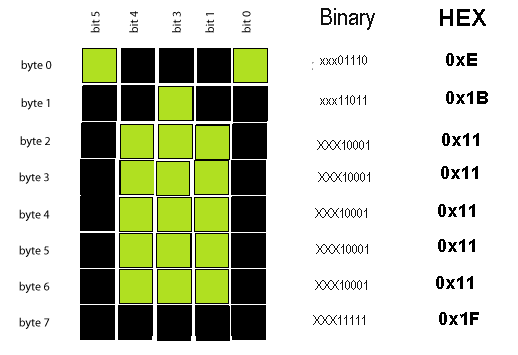
a standard 5×8 dots font is being shown in the image as you can see there are total 8 bytes of data on the whole to decide pattern of the font.
as yo can see all you need to do is decide the first row pattern like in the example image of a battery symbol
in first row the first pixel is off so lsb bit 0 is 0 and pixel 1 is on so bit1 is 1 and pixel 2 is on so bit 2 is 1
this method apply on each row of the font ( 8 rows ). which gives us total 8 bytes of data first msb 3 bits are always 0.
you can also use this web tool to decide this pattern and code. CLICK HERE
now we have our pattern to be written to the CG RAM.
the writing sequence is like this
- set CGRAM ADDRESS by lcdCmd(0x40);
- send the byte 0 lcdData(0x0E);
- send the byte 1 lcdData(0x1B);
- send the byte 2 lcdData(0x11);
- send the byte 3 lcdData(0x11);
- send the byte 4 lcdData(0x11);
- send the byte 5 lcdData(0x11);
- send the byte 6 lcdData(0x11);
- send the byte 7 lcdData(0x1F);
if you want to send the next custom font to lcd then not need to set DD RAM addresses again . it will automatically increment to next location.
now we are ready to display this font on to lcd. but keep one thing in mind you should get back to DD RAM, to display this data on to screen . this can be done by setting DD RAM address. like for 16×2 char lcd first, row first character send lcdCmd(0x80);
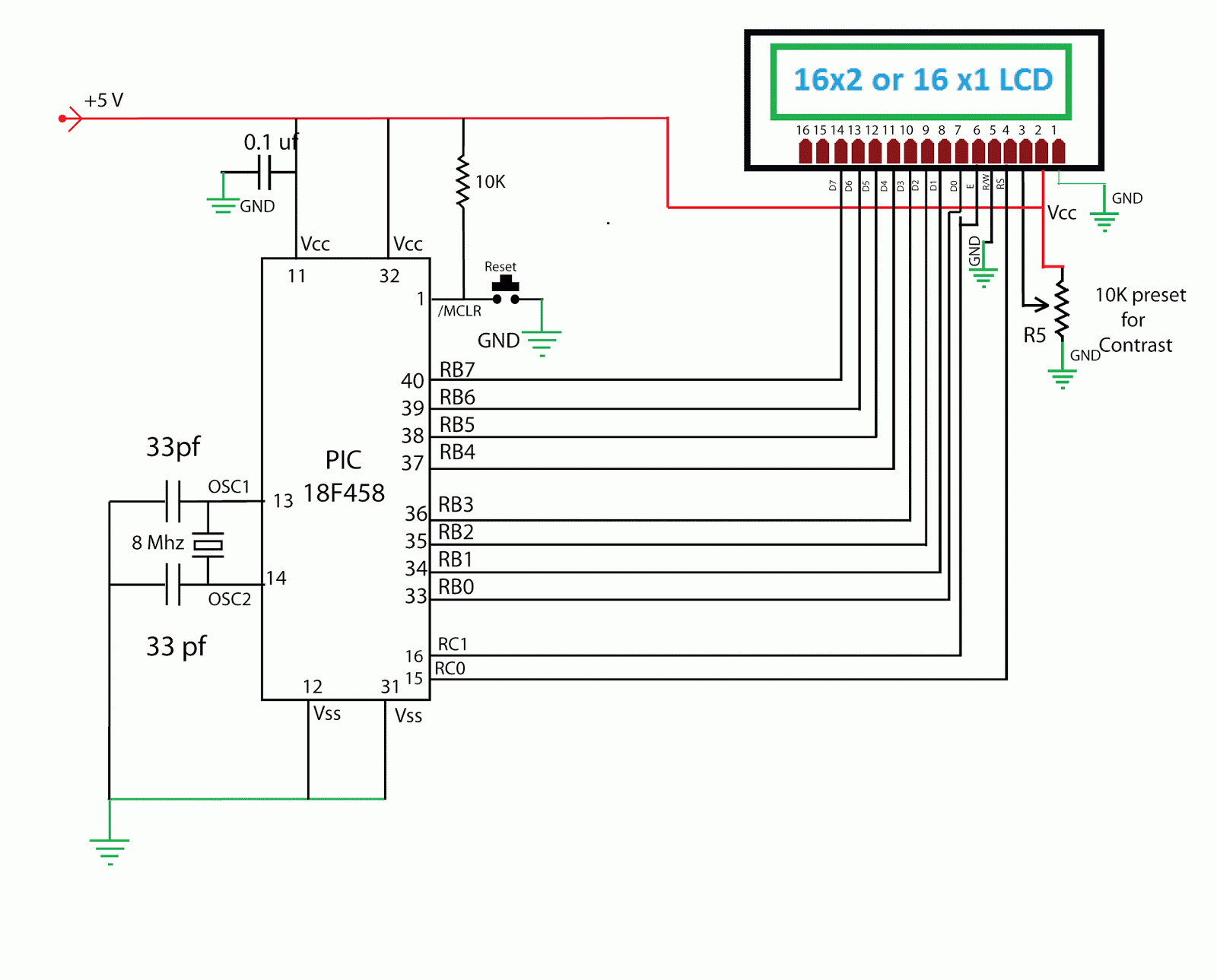
implementation with PIC MCU
CLICK HERE TO DOWNLOAD SOURCE CODE N HEX


