SETTINGS
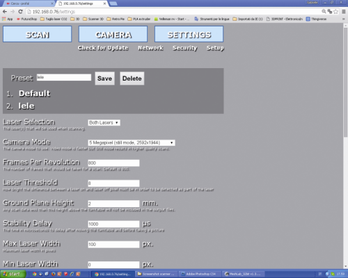
In this section it is possible to set some Preset, custom values and to save them at leisure, that is to say, to execute the settings of all the operating parameters described as follows.
The Laser Selection defines the laser that will be used during the scan: the left one (SX), the right one (DX) or both.
The Camera Mode sets the video camera’s shooting mode (the Video mode is faster, while the Still one allows for a higher scan quality). The values are predefined in the specific drop-down menu, it is possible to access it by clicking on it, they correspond to as many modes: 0.3 MP (640×480 video mode); 1.2 MP (1.280×960 video mode); 1.9 MP (1.600×1.200 video mode); 5 MP (2.592×1.944 video mode); 5 MP (2.592×1.944 still mode).
Frames Per Revolution indicates the number of frames shot during the scan (800 is the default value). A greater number of “shots” per revolution determines a more accurate scan and also an increase as for the scan times and for the size of the generated file.
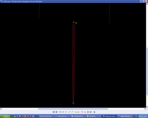
The Laser Threshold defines the brightness value that the pixel must have (when it is hit by the reflected laser’s light) in order to be detected; if the object has a surface having different reflection coefficients (and since a single threshold value has been set) the video camera will be blinded in the points in which the laser is reflected the most, while other dots will turn out to be dark or the video camera will lose the dots in which the laser beam is absorbed (because of the colour or the material’s porosity). In the first case the reflection will generate a cloud of dots scattered in the space in front of the zone hit by the laser beam, while in the second one a “hole” will remain in the obtained module. If the value is too low the video camera will be more sensitive, but the risk is that a cloud of dots that “dirties” the object is created around the point hit by the laser (the model will then have to undergo a “focused removal” of the unnecessary dots by means of a 3D processing software such as, for example, MeshLab) while if it is too high the video camera will risk to not “see” or to see only partially the laser beam on the object’s surface. In order to verify if the set value is a good one or not please use the “Test” function: after having placed the object on the plate, please click on the “Test” button; after a few seconds an image (.png) will be returned, it shows how the video camera sees the laser beam(s) on the object’s surface .
If the line(s) turn(s) out to be discontinuous (dotted) we need to lower the value, while if they turn out to be jagged or very confused (they have an aura) we need to raise it.
Ground Plane Height defines the scanning plane’s height under which the scanner may not carry out the scan.
Stability Delay defines the time (expressed in microseconds) that the video camera has to wait, after the plane’s rotation, before shooting another picture.
Max Laser Width defines the maximum width of the laser’s line (expressed in pixels).
Min Laser Width defines the minimum width of the laser’s line (expressed in pixels).
Generate PLY File converts the scan in a PLY cloud of dots.
PLY Data Format defines the PLY file’s format (Binary or ASCII).
Generate STL File supplies the scan in a .stl file.
Generate XYZ File converts the scan in a XYZ cloud of dots.
Separate the Lasers Calibration is a debug option, used in order to separate the images obtained by the two lasers, and distinguishes them by using different colours (it requires PLY).
Enable Burst Mode enables the video camera’s burst mode, during the still mode acquisition.
Create Base for Object adds a flat base to the object, so to simplify the 3D printing.


