Mechanics and optics
We will now move on to talk about the scanner’s mechanical part, that is the set of the plastic printed parts (for example, as created by our 3Drag) and assembled by means of iron threaded rods and bolts; the main blocks are the base (that contains the electronics and the video camera at the center and the two linear lasers at the sides), and the plate that supports the object: it is a turning one on a bushing that has been secured to a plastic support that is connected to the base by means of threaded rods. The plate may be obtained from a plexiglass or forex disk (a 4 mm thick one) but it may also be in PLA and therefore a printed one; after having applied a black cover sheet, please locate its center and highlight it as a dot made by means of a permanent marker.
The linear lasers are Class 3A, red light semiconductor ones (with a wavelength of 650 nm) of the 2510-LASER5MWLINEA kind from Open store; each one of them develops an optical power of 3 mW and requires a power source having a DC voltage of 4÷6 V (it absorbs 280 mA). The laser integrates a collimating aspheric lens in order to direct the light to a single point, that is then transformed into a line thanks to a cylindrical acrylic lens, placed at the exit of the laser ray, so to create a light beam having a triangular section with an opening of about 45°.
How it works
In order to acquire the object’s shape, our system executes a superficial analysis of the same, by rotating it on a plate by a degree (or a fraction of it) at a time, while the light of a linear laser is directed towards it; the laser projects a vertical line that covers the whole height of the object to be scanned and the reflected light reaches a video camera that acquires the resulting images and sends them to the dedicated software. In order to acquire all the needed information, the object is rotated by an angle, chosen at your discretion, even though usually a complete rotation (360°) is carried out. The program allows to establish the number of steps that the NEMA 17 motor has to carry out in order to complete a whole revolution (360°) and up to 6,400; our stepper motor is a 200 steps per revolution one, and when driven by the shield, it carries out a step with every 32 pulses on STEP that come from Raspberry Pi 2; therefore 200 steps multiplied by 32 gives 6,400.
The linear laser beams are inclined between them by 60° on the horizontal plane, therefore the video camera, since it is centered with respect to the two lasers, is placed with a 30° angle with respect to the beam of each one of them.
The scanner has to operate in an environment that must not be excessively well-lighted, so that there is a clear contrast between the zone hit by each laser’s line and the surface of the object to be scanned.
When the scan is started, Raspberry Pi 2 will begin to acquire the images (frame) supplied by the video camera, with a periodicity set by the software: the default value is 800 per whole revolution of the plate (and therefore, of the object), but we also tried to operate with 2,000 frames per revolution.
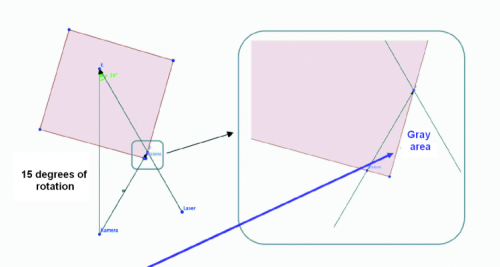
The need to use a second laser arises when you need to scan, for example, a cube: in this case, in fact, when using a single laser only, some grey areas are created because of the misalignment (that is to say, the different angle with which the two elements address the object to be scanned) between the video camera and the laser.
In this specific case, since the two are not on the same axis, during the rotation there are some zones in which the ray is darkened by one of the faces and it does not reach the video camera, thus preventing the perception of the reflected ray and therefore determining some “holes” in the model acquired. If we add a second laser, tilted by 30 degrees in the counterclockwise direction, the grey areas disappear: in fact, when the object rotates and goes beyond the critical angle of the first laser, the grey area is scanned by means of the second one. As for the acquisition of objects that do not possess faces such as to hide the laser’s line from the eye of the video camera, it is possible to use only one laser for the scan.
Let’s see therefore how the acquisition is carried out: for each frame, the reflection of the laser’s line (that is vertical and represents a very small slice of the surface) is taken into consideration; at each rotation therefore a frame is acquired, the latter has a lighted segment that falls each time in a position that is always different, until the desired surface is completed. For each frame, Raspberry Pi 2 analyzes the lighted zone, and discards the rest of the image, that is used just for the purpose of verifying the correct sequence for queueing the slices; by putting the slices together the image is reconstructed.
The software
Let’s move on to talk about the program that runs in Raspberry Pi 2 under the Raspbian operating system and that is named FreeLSS, as previously anticipated: it may be downloaded from the https://github.com/hairu/freelss website. In order to access it from the network, please open the browser and write the IP address assigned by Raspberry Pi to it, then press Return; once the network connection has been established, the main screen will appear: we will now describe its various sections.


